

- 5levers
- 6levers
- 7handles
- 8handles
- 9pivot
- 10arms
- 11arms
- 12arms
- 13arms
- 14slots or notches
- 15slots
- 17slots or notches
- 22notches orslots
- 23notches orslots
- 24cutting edges
- 25cutting edges
- 26member
- 28rivets
- 29rivets
- 31hole
- 33bow-shaped spring
Description
w. H. NIoHoLLs.
" GLIPPER.
APPLIOATION FILED JULY 15, 1910.
1,021,999. LPatented ,x pr.2,1912.A
WALTER H. NICHOLLS, 0F CHARLESTOWN, MASSACHUSETTS?.
CLIPPER.
Specification of Letters Patent` Patented Apr. 2, 1912.
Application filed July 15, 1910. Serial N o. 572,125.
To all whom t may concern: Y l
Be it known that I, WALTER H. NrcHoLLs, a citizen of the United States, residing at Charlestown, in the county of Suffolk and State of Massachusetts, havejinvented new and useful Improvements in Clippers, of which the following is a specification.
This invention relates to improvements in cutters, clippers and the like, and while the device of my invention may be employed for a variety of purposes, it is particularly intended and adapted for use 'as a nail and cuticle clipper. y
One of the objects of my invention is to provide a clipper in which the cutters may be readily removed and replaced, thisbeing of great advantage where it is desired to substitute cuticle cutters forv nail cutters and vice versa.
Another object is to provide means for attaching the cutters to the handle levers so that the cutters shall be carried positively in both directions by the levers Another object is to provide means to pre.- vent relative lateral displacement of the cut ting edges of the cutters.
Still other objects and advantages will appear hereinafter. i
The invention consists in the novel features of construction vand inthe combination and arrangement of parts set forth in thev following specification and pointed out in the claims. n
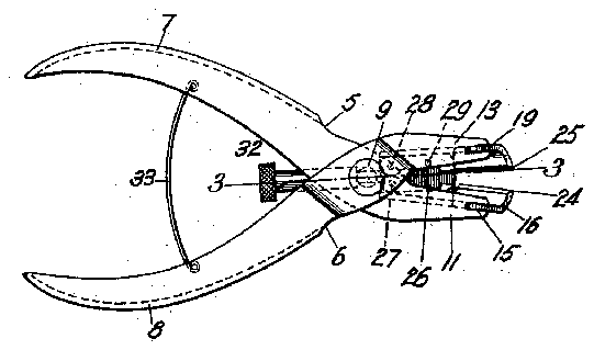
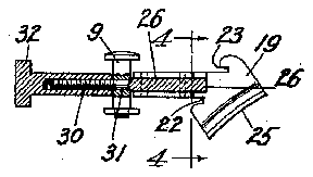
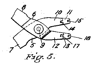
Referringv to the drawing: Figure 1 is a side elevation of a c-lipper embodying my invention. Fig. 2 is a plan view of the particularly clipper shown in Fig. 1. Fig. 3 is adetailplan section taken online 3-3 of Fig. ,2. Fig. 4 is a detail sectional view taken on line 4-4 of Fig. 3. Fig. 5 is a side eleva-V tion of t-he levers with the cutters removed, the handles of the levers being partly broken away.
Like numerals refer to like part-s throughout the several views of the drawing.
In the drawing, 5 and 6 are two levers which may beof any suitable construction and which, in the present embodiment of my invention, are formed of sheet metal provided, respectively, with hollow handles 7 and 8. kThe levers 5 and 6 are crossed' and are pivoted to each other by a pivot 9 which passes therethrough. The lever 5 is provided with two parallel arms 10 and 11 and, in like manner, the lever 6 is provided with two parallel arms 12 and 13.
The arms 10 and y11 are provided, respectively, with slots or notches 14 and l5 to receive a suitable cutter 16 and, in like manner, the arms 12 and 13 are provided, respectively, with slots or notches 17 and 18 `to receive a suitable cutter 19. By reason of this construction, the cutters are carried positively in both directions by the swinging movement of the levers 5 and 6.
Thev cutter 16 is provided with notches or slots 2O and 21 which receive the arms 10 and 11, respectively, and, in like manner, the cutter 19 is provided with notches orslots 22 and 23 which receive the arms 12 and 13, respectively. Thus the cutters or jaws of the clipper are held against lateral displacement with relation to the levers in which they are respectively mounted.
Preferably, though not necessarily, the jaws or cutters are offset, as shown in Figs. 1 and- 3, or, in other words, their cutting edges 24 and 25 are Qbliquely arranged, thus affordinoa a more convenient angle of the handles F and 8 when operating the clipper. In case the cutting edges are thus obliquely arranged, the arms 11 and 13 will .bel eX- tended to a greater length than the arms 10 and 12, as shown in Figs. 1 and 5a-nd in this way the arms 11 and 13 reinforce their vrespective lcutters lor jaws well out toward Fig. 4, and inclosing a member 26 constituting a guide block. To this member or guide block, the jaws are connected in any suitable manner, the jaw 16 being shown pivoted at 27 to said member and the jaw 19 being secured to said member by rivets 28 and 29.
When the jaw 16 rocks to and fro with relation to the jaw 19, its inner parallel faces slide in contact with the faces of the 'member or guide block 26 and in this way the cutting edges 24 and 25 are prevented yfrom becoming displaced laterally with relationto each other even though there may,
be any tendency for thev arms of the levers 5 and 6 to yield laterally. 'Ihe function of the member 26, however, is obviously not solely that of a guide block, for it will be seen and understood that this element constitutes a mounting for the cutters or jaws 16 and 19 so that the cutters when withdrawn from the slots 15 and 18 remain att-ached to the member 26. Moreover, the member 26 serves as a mounting for the rod 30 connecting the cutters to the pivot 9. Hence, the member 26 serves as a means for forming a unitary structure of the cutters 16 and 19 and the rod 30 by which the cutters are connected to the pivot 9. It will thus be seen that merely the removal of the nut 32 permits the removal of these parts as a unit, since they are mounted upon the member 26.
The jaws 16 and 19 are held inplace in any suitable manner as, for example, by providing the guide block Q6 with a screwthreaded shank 30 extending through a hole 31 provided in the pivot 9. A thumb-nut 32 having screw-threaded engagement with the shank 30 draws the jaws toward t-lie pivot 9 and holds them firmly in place, yet permitting the aws to be very conveniently removed and replaced. The advantage of this is that the user may be provided with two sets of jaws identical with each other in all essential respects, one suitable for clipping the nails and one suitable for cutting the cuticle and the change from one to the other can be made very quickly and conveiiiently.
The handles 7 and 8 are connected 'to each other by a bow-shaped spring 33 suitably secured at its opposite ends to said handles, respectively, the form of this spring being such that when the handles are forced toward each other to carry the cutting edges toward each other, the spring yields toward the free ends of said handles and when the handles are released, the spring assumes the shape shown in Fig. 2. This spring, however, it will be noted, holds the handles in a certain position and prevents them from being spread apart and prevents the jaws from being spread apart unduly.
Having thus described my invention, what I claim and desire by Letters Patent to secure is:
1. A clipper having, in combination, a pair ot' crossed levers provided respectively with slots, a pair of cutters provided with opposed cutting edges and located in said slots respectively, a pivot on which said levers are `fulcrumed, said pivot having an aperture and being located laterally of and external to said cutters, and means to attachably and detachably attach said cutopposedl cut-ting edges and located in said slots, respectively, a member on which one of said cutters isimounted, a pivot on which the other of said cutters is pivoted to said `member, a pivot on which said levers are tulcrumed, and means forming an attachable and detachable connection between said memberand the last-mentioned pivot.
3. A clipper having, in combination, a pair of crossed levers provided respectively with slots, a pair of cutters provided with opposed cutting edges and located in said slots, respectively, a member on which one of said cutters is mounted, a pivot on which the other of -said cutters is pivoted to said member, said pivot being provided with an Iaperture, a pivot on which said levers are `fulcrumed, and means extending from said member through said aperture and forming an attachable and detachable connection between said member and the last-mentioned pivot.
f1. A clipper having, in combination, a pair ot' jaws, an 4element to which one of said jaws is pivoted and on which the other of said jaws is suitably mounted, a pair of :crossed levers connected respectively to said jaws to operate the same, a pivot on which said ylevers, are pivoted to each other, a screw extending from said element through said pivot, and a nut having screw-tlireaded engagement with said screw on the opposite side of said pivot to that on which said jaws are located.
5. A clipper having, in combination, a
epair of crossed levers, a pivot on which said levers are pivoted to each other, said pivot being provided with an aperture, a pair of `jaws connected, respectively, to said levers to be operated thereby, a block on which said jaws are mounted, a rod extending from said block through said aperture, and a nut having screw-threaded engagement with said rod on the opposite side of Vsaid pivot to that on which said jaws are located.
In testimony whereof I have hereunto set my hand in presence ot' two subscribing witnesses.
WALTER H. NICHOLLS. lVitnesses Louis A. JoNns, SADIE V. MOCARTHY.
Copies of this `patent may be obtained for ve cents each, by addressing the Commissioner of Patents, Washington, D. C.