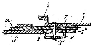
- 3apertures
- 4protuberances
- 5protuberances
- 6rivet
Description
F'igozmirso.
V To all y1071307214115 may concern:
Be-itlmown thatfI`,fPL1-NY GATUGGI, a citi'y zen of 'the United States, residing in the 'city of "Newark, county of EsseigState of. New-Jersey, haveinvented certain new-and,y Vuseful Improvements inV Nail-Clippers, `off `lwhich the Vfollowing isa ktrue fand accuratedescr-iption, such as Will enable thosev skilled ,in-theeart to-r make and use Vthe same. y The-obj ect: of kmy invention is A to provide ahandy-and usefulv device,fcapable of being folded/and locked, so -as to occupy the l least possible space inthe pocket Vand yetfinclude all pf the parts needed in trimming the linger nai s.
` UNITED STATES PATENT CATTJ'CGI,` OF`NEWARK,NEW"JERSEY, ASSIGFN'OR TO A. F. MEISSELBACH cpBRO.,
OF NEWARK, NEW JERSEY, A 'CORPORATIONOF`NEW 'JERSEY'. v
f NAILCLIPPER.
- Another object is to provide a-,device having the' cutting j aWs, hereinafter designated fcutters, 4arranged diagonally along both. .edges of the=operating levers,betweenthe f in order to lgive ashearing -actionto the cutltersrather than a direct cutting action,-and .also to -avoid lthe transmission of power -through morethan one hinge, as found in 25 .t Y
hinge and the .point of application of power,
theold design. v
Referring to the accompanying drawing,
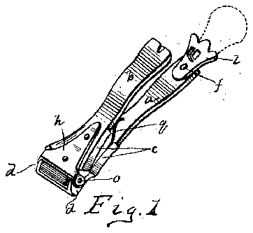
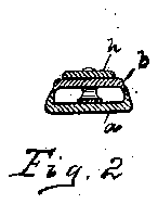
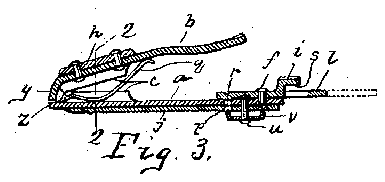
vWhich' forms a part-of this'specification- `-F1gure l represents a perspective 'view of they device showing the parts open. Fig. y2 represents a sectional viewthrough line 2,2
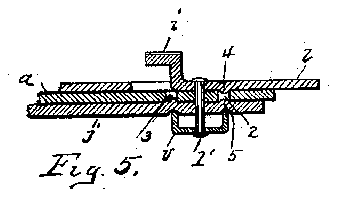
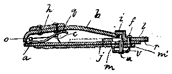
fof Fig. 3.` Fig.v 3 represents a longitudinal 4section with the device open. Fig 4'fis the same With the device closed. Figs. V5 `and 6 illustrate tivo distinct modifications of the mann-er of applying-the file 'and the eXten- .-sion handlesto one ofthe cutterlevers.
. The -device consists essentially vof thetwolevers, wand b, hinged-together bythe pivot foy;A to Which the other parts are suitably secured, as hereinafter described.` Thelevers,
and7b,'are preferably-composedof sheet -Y metalstamped in such a manner as to form `the "cutters, c, andthehingel'ugs d, through 'which the v pivotio,` isf passedy and secured in a suitablemanner.V f Y I find it practically impossible to ac- ;cur'ately :.-aline 'the `cuttingledges when the hinge lugs 'of 'the l lever JZ), and the lever ab,
-tures and m, of
Patented May 21,1912.
Application Vfiled March 7, 1910.r Ser'a1'No.`547,926. p
fault,^I clamp the two-members, aand b, together, so that the cutters Aengage `properly, and then secure .thehingei plate fh,: :to the lever in some suitable manner, .as,"for
example, byA riveting, soldering, or elec-i1,u y tric Welding.
11pm-'Ventthelnlembers, a: and opening undlll7 through the action .Ofl'fthe spring g, by bendingtheV lever b idovvnvvard q fromV a point beyond the hingey pivot, soithatr` .itsvextremity y-Will engage -against the eX- tremityl e, ofthe rlevera, this forming a stop. I alsofndit convenient to providefa handle yt-o prevent the-device from slipping from the hand While in use. I do this bypivot ally securing the handle 7, by means ofthe pin f, Which is convexlyheaded for apjurpose hereinafter described, in su'cha manner -as' to allov:7k 1t' to swing between Athe levers a and b. In order .to hold the handlelin; 1
positiondwvhile the device is in.use,fI provide the projection r to-engage kor snap intogthe aperture -p,.located. conveniently,y in Athe lever fa.' The handlerl has one Aend'thereofy struck vup yto formy the rkeeper z' whichlatterispro-y -vi'ded with the grooved projection af `The lever o has a notch at its rearextremity, and When the' handle Z-.is swung into the position indicated inV Fig. 4, the'projection s will snap into saidnotch and -therebylockz` yWasher @,-the' nail filej, Which terminates in y 2a point for manicuring purposes. Thexilej,
is held either in an open ork closed position by snapping one of theapertures, m or m',
'situated'on either side of ythepivot uyover described, and by Vthe slight forcing `of the spring-Washer o.. `4This washer, @is provided With tongues devised to tin the 4aperthe file j, thus preventing Aitfrom,rslippi1ig.V
theconveX-head of the -pin f,rasheretofore of power, and is operated by simply pressing the levers a and b together, thereby causing the cutters, c, to engage and perform the work required.
In the modification illustrated in Fig. 5 I have shown the handle Z and the file j secured to the lever a by means of a single pivot pin Z, and I locate apertures 2 and 3 on each side of said pivot pin Z in the lever a as shown. In the ile j and handle Z, I locate the slight protuberances, 5 and 4, respectively in such a position as to snap into one or the other of the apertures 2, 3, when either or both the handle or file are turned upon the pivot pin Z. These protuberances 4 and 5 are produced by indenting the face of the part so as to force the metal into a slight projectionupon its opposite side as shown.
From the above description it will be noted that when the handle Z .is swung into the position shown in Figs. l and 3, the spring will open the levers and cutters while the handle Z will sufficiently lengthen thelever a to give the user a hold thereon so that he may easily manipulate the lever b to operate the device. The location of the cutters in a diagonal line along the edges of the levers also adds to the convenience of the device in use.
In Fig. 6, I have shown a still further slight modification in which both the handle Z and the file 7' are pivoted to the lever a by the single pivot pin Z. In this case I provide the handle with the small rivet 6 convexly headed on both sides as shown. In the handle Z I locate the aperture 7 and .in the le j the two apertures 8 so placed as to register with the heads of the rivet 6 as clearly illustrated. The tongues on the washer v are received into the aperture 8 as described in connection with Fig. 4.
In each of the constructions illustrated in Figs. 5 and 6, the handle a should be slightly longer than the handle Z) so that the rectangular keeper I will properly register with the notch in the said handle ZJ.
I claim:
1. In a nail clipper, the combination of a pair of rigid levers hinged adjacent to their forward ends, stops upon said forward ends to limit the opening of said levers, shearing cutters formed upon the side edges of said levers at the rear of the hinge, a spring for opening said levers and a keeper pivoted to one of said levers, whereby said keeper may be turned laterally to engage the other lever to hold both levers closed.
2. In a nail clipper, the combination of a lever provided with hinge lugs, and shearing cutters upon its side edges, a hinge plate provided with hinge lugs pivoted to the hinge lugs of said lever, a rigid lever rigidly secured to said plate, said lever having shearing cutters thereon to coperate with the cutters upon the first named lever plate, a spring for normally holding the levers open and a pivoted keeper for normally holding said levers closed.
3. In a nail clipper, the combination of a pair of rigid levers pivoted together adjacent to their forward ends, a curved extension upon one of said levers forward of its pivot, a straight extension upon the other lever forward of its pivot, said extensions forming a stop to limit the opening of said levers, cooperating shearing cutters upon the side edges of said levers at the rear of their pivot, a spring for opening said levers and a keeper for holding said levers closed.
4. In a nail clipper, the combination of a pair of levers pivoted together adjacent to their extremities, a curved extension upon one, of said levers to form a stop in connection with a corresponding straight extension upon the other lever, a spring for normally holding the levers open against said stop, a keeper pivotally connected with the opposite extremity of one of said levers to engage and hold the other lever closed, and coacting shearing cutters located diagonally upon the edges of said levers adjacent to their pivot.
5. In a nail clipper, the combination of a lever having hinge lugs upon its edges adjacent to Vone end thereof a hinge plate having lugs thereon pivoted to the lugs upon said lever, a second lever rigidly secured to said hinge plate, shearing cutters arranged diagonally upon the edges of said levers to coperate in pairs, a spring for normally holding said levers and cutters open and a keeper pivoted to one of said levers to cooperate with the other lever to hold them closed.
6. In a nail clipper, the combination of a.
pair of levers hinged together and provided with curved shearing cutters along their side edges, an extension handle pivoted to one of said levers, a projection upon said extension handle, said lever being provided with a notch to receive said projection, a spring washer secured to said handle pivot for resiliently holding said handle in open or closed position in alinement with said lever.
7. In a manicuring device, vthe combination of a pair of levers hinged together and provided with shearing cutters, one of said levers having an aperture therein, a nail file pivoted to one of said levers and having protuberances thereon to engage said aperture in said lever, and a spring washer for resiliently holding said file in either open or closed position in alinement with said lever.
8. In a manicuring device, the combination of a pair of levers hinged together and each provided with a pair of shearing cutle or both of them in either open or Closed position in alinement with said lever.
This specification signed and witnessed this 2d day of March 1910. f
PLINY CATUCCI.
ters, one of said levers having an aperture therein, an extension handle and a nail file, each pivotally secured to one of said levers and each having protuberances thereon to engage With said aperture in said lever, a spring Washer having relativelynon-rotative engagement With said nail file for resiliently holding either said handle or said nail- Vitnesses: Y
MERVIN L. SANDERS, W. B. WALTZINGER.
Copies of this patent may be obtained for vc cents each, by addressing the Commissioner of Patents,
Washington, D. C.