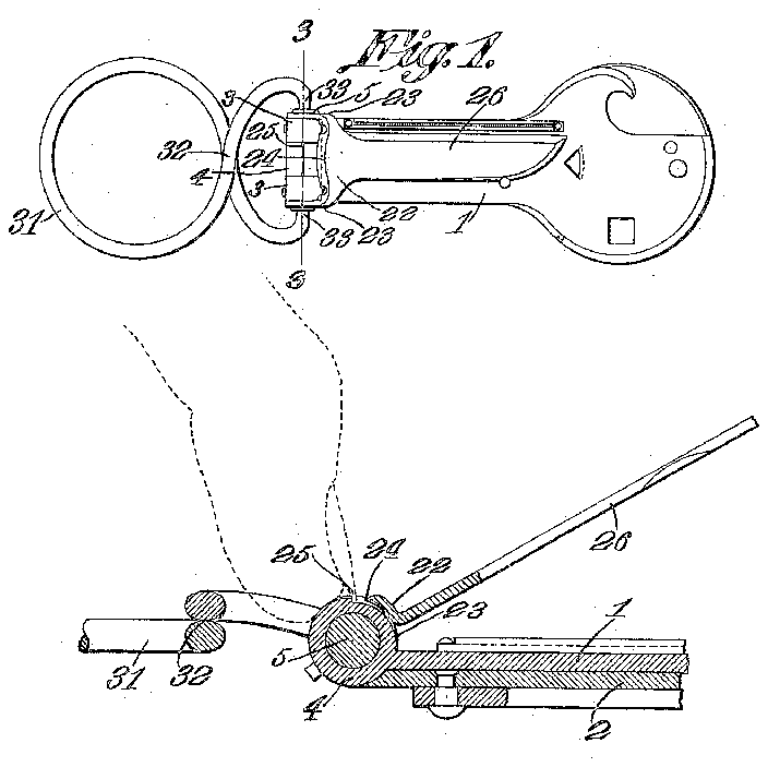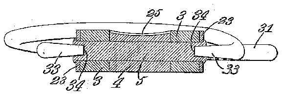

- 1leaf
- 2leaves
- 3butts
- 4butt
- 5hinge pin
- 22yoke
- 24shear edge or cutter
- 25shoulder or cutter
- 26knife blade
- 28steps
- 31loop
- 32crossed portions
- 33pintles
- 34sockets
Description
R. C. MINER.
FINGER NAIL CLIPPER.
APPLICATION FILED AUG.5, 19I3.
1113mm 1 Patented. A111". 13, 1915.
1 W W 0 v Witnesses W 1 Inventbr zfiw w THE NORRIS PETERS CO4, PHOTO-LITHQ. WASHINGTON, D c.
mar sits PATNTD oirribn.
RAYMOND G. MINER, OF
FAITH, SOUTH DAKOTA, ASSIGNOLR. OF ONE-HALF TO HANS P. HANSON, OF FAITH, SOUTH DAKOTA.
FINGER-NAIL CLIPPER.
Specification of Letters Patent.
Patented Apr. 13, 1915.
Application filed August 5, 1913. Serial No. 783,168.
To all whom it may concern Be it known that I, RAYMOND C. 'MINER, a citizen of the United States, residing at Faith, in the county of Meade and State of South Dakota, have invented a new and useful Finger-Nail Clipper, of which the following is a specification.
The present invention appertains to fingernail clippers, and is particularly an improvement over the combination tool disclosed in my copending application filed March 10, 1913, Serial No. 753,336.
One of the objects of the present invention is the provision of a novel finger nail clipper for use in a combination tool.
Another object of the present invention is to provide a key ring, or the'like, which may be grasped or held in the hand to assist or facilitate clipping the finger nails.
Nith the foregoing and other objects in view, which will be apparent as the description proceeds, the invention resides in the combination and arrangement of parts and in the details of construction hereinafter described and claimed, it being understood that changes in the precise embodiment of the invention herein disclosed, can be made within the scope of what is claimed, without departing from the spirit of the invention.
The present invention has been illustrated in its preferred embodiment in the accompanying drawing, wherein Figure 1 is a plan view ofthe device. Fig. 2 is an enlarged sectional detail taken through the finger nail clipper. Fig. 3 is an enlarged sectional detail taken on the line 3-3 of Fig. 1.
1n carrying out the invention, reference being had in detail to the drawing, there is provided a pair of flat sections or leaves 1 and 2, which are elongated, and which have their adjoining ends hinged together. 1n order to hinge these leaves together, the inner end of the leaf 2 is provided with a pair of butts 3, and the leaf 1 is provided with a single round butt or enlarged portion 1 fitting snugly between the butts 3, a hinge swing snugly around the hinge butts, and that edge of yoke 22 remote from the leaf 1 is provided at its intermediate portion with a shear edge or cutter 24 cooperating with a shoulder 25 formed on the butt 4 approximately at right angles to the leaf 1. The shoulder 25 provides a shear edge or cutter cooperating with the shear edge or cutter 24 of the yoke, the shear edges or cutters being so curved as to accommodate the finger nails and to properly trim them. The other or opposite edge of the yoke 22, or that edge of the yoke disposed adjoining the leaf 1, is provided with a knife blade 26 extending radially from the hinge butts or hinge pin, and forming a handle for the yoke or its cutter.
WV hen the finger nail clipper and knife blade forming a part thereof, are not in use, the blade 26 is adapted to be swung against the leaf 1.
The key ring embodies a wire loop 31, the end portions of which are crossed, as at 32, and the ends of which are bent back toward each other, and tapered, to provide the pintles 33. The ends of the hinge pin 5 are provided with sockets 34: adapted to receive the pintles 33, it being noted that when the sides of the loop 31 are compressed or forced together, the pintles 33 will be spread so as to readily engage over the ends of the hinge pin, the loop 31 having an expansive tension so as to spring the pintles 33 into the sockets 34. When the pintles are thus engaged to the ends of the hinge pin, the loop 31 may be swung about the hinge butts, toward the respective leaves 1 and 2. The loop 31 may be readily removed, as above intimated, and the keys or other articles may be readily engaged on the loop 31, by slipping them over one end of the loop, and working them through the crossed portions 32, as will be clearly apparent. The crossed portions 32 are normally in contact, to retain the keys or other articles within the loop 31 proper.
Particular attention is directed to the novel combination with the hinged leaves, of the finger nail clipper, knife blade, and key ring. The use of the knife blade and key ring of themselves will be clearly apparent, but it is to be noted that the knife blade and key ring are of particular advantage in connection with the finger nail p 24 over the shoulder or cutter 25.
clipper. As above stated, the knife blade 26 the leaves land 2 being held together in any suitable manner, while the knife blade or handle 26 is swung so as to shear the cutter By inserting the finger nails over the shoulder or cutter 25, the cutter 24 in being moved toward andover the cutter 25, will sever a predetermined amount from the end of the finger nail. By repeating this operation, the finger nail or finger. nails may be conveniently clipped or trimmed, as desired. It is to be noted that the movement of the yoke 22 is limited by the steps 28, and it is to be noted, that if desired, the key ring 31 may be held in the hand, the finger nails of which 1 are to be trimmed, so as to steady the. hand,
in order that the finger nails may be conveniently held on the, shoulder or cutter 25 while the handle or knife blade 26 is swung or manipulated. Thus, the key ring 31 provides a handle, having a. yoke portion 3238 pivoted to the ends of the hinge pin 5, and whereby'the handle 01' key ring may swing around that end of the, leaf or memher '1 having the cutter 25.
Having thus described the invention, what is claimed as new is: i I 1 In a fingernail clipper, a member having a round enlarged portion at one end provided with a cutter, and a yoke pivoted to the said enlarged portion to swing snugly around the same and having a handle, the
yoke having a cutter adjacent the, said enlarged portion, arranged to shear over the aforesaid cutter.
2. In a fingernail clipper, a member having a round butt at one end, the butt hav ing a shoulder forming a cutter, a pin on gaged through the butt, and a yoke terminally engaged over the ends of the said pin to swing snugly around the butt, one edge of the yoke having a cutter adjacent the butt to shear over the aforesaid cutter, and the yoke having a handle.
3. in a fingernail clipper, a member having a cutter at one end, a member pivoted to the said end of the said member and having a cutter to swing around and shear over the aforesaid cutter, and a handle pivoted to the'said end of the first mentioned member to swing around the said end.
4t. In a fingernail clipper, a member having a butt at one end, the butt having a shoulder forming a cutter, a pin engaged through the butt, a yoke terminally engaged over the ends of the said pin to swing around the butt, the yoke having a cutter to shear over the aforesaid cutter, and a handle having a yoke portion pivoted to the ends of the said pin.
In testimony that I claim the foregoing as my own, I have hereto afiixed my signature in the presence of two Witnesses.
RAYMOND O. MINER.
Witnesses:
F. R. AYER, H. V7. DAVIS.
Copies of. this petentana y be obtained for fivev cents each, by addressing the Commissioner of Patents,
' I v Washington, D. C.