

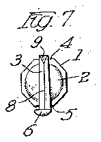

- 3blade
- 4edge
- 5blade surface
- 6flange
- 7toe portion
- 8cutting edge
- 9edge
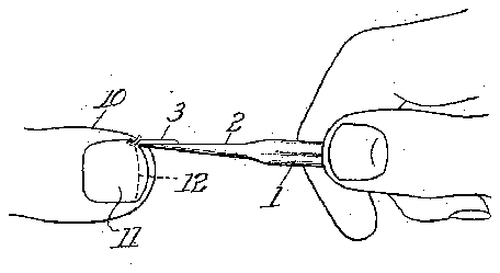
- 10portion
- 11nail
- 12dotted line
Description
F. 0. PEASE.
CHIROPODISTS 0R SURGEON'S INSTRUMENT. APPLICATION FILED SEPT.24, 1913. RENEWED DEC. 6. 1911.
Patentd Jan. 29,1918.
FREDERICK 0. PEASE, OF CHICAGO, ILLINOIS.
QHIROPODISTS 0R SURGEONS INSTRUMENT.
Application filed September 24, 1913, Serial No. 791,509.
To all whom it may concern:
Be it known that I, FREDERICK O. Pnesn, a citizen of the United States, residing at Chicago, in the county of Cook and State of Illinois, have invented certain new and useful Improvements in Chiropodists or Surgeons Instruments; and I do hereby declare the following to be a full, clear, and exact description of the invention, such as will enable others skilled in the art to which it appertains to make and use the same.
My invention relates to surgical instruments and more particularly to a type of knife or chisel adapted for use by chiropodists. The prime object of my invention is to provide a cutting instrument equipped with a flange adapted simultaneously to guide the instrument to protect the cuticle or tissue adjacent to that which is being cut by the knife edge of the instrument, and to 7 effect a separation of a part of the severed cuticle, nail or tissue from the tissues formerly contiguous thereto. Another object is to equip the blade of a surgical instrument with a guide flange so disposed with reference to the handle of the instrument as to permit the ready and accurate operative manipulation of the said flange by a rotary movement of the handle.
The instrument of my invention is particularly adapted for use in operations upon ingrowing toe nails and tissues contiguous thereto, including operations on the periosteum; and is shown in an embodiment particularly adapted to this application in the accompanying drawings, in which Figure 1 is a longitudinal elevation.
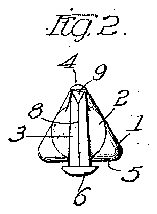
Fig. 2 is an enlarged end view of the same.
Fig. 3 is an enlarged fragmentary plan view of the same.
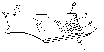
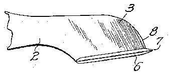
Figs. 4 and 5 are enlarged fragmentary elevations of the blade end of the instrument, showing modifications thereof.
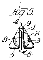
Figs. 6 and 7 are end views showing a modified form of guide flange and of the handle, respectively.
Fig. 8 is a perspective view showing the instrument as used in operation upon a toe nail.
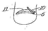
Fig. 9 is a view showing the operation of the guide flange in facilitating the removal of a portion of an ingrown toe nail.
Fig. 10 is a cross section of a modified form of handle.
Specification of Letters Patent.
Patented J an. 29, 1918.
Renewed December 6, 1917. Serial No. 205,894.
In the embodiment of'Fig. 1, the instrument of my invention consists essentially of a straight sided handle 1 of triangular section having a contracted neck portion2 connecting the said handle with a blade 3, the said blade being relatively thin and having its face portions disposed approximately in planes passing through one of the longitudinal edges 4 of the triangular handle and at right angles to the blade surface 5 of the handle opposite to the said edge 4. The
blade 3 has at one edge a flange 6 extending I substantially longitudinally of the handle and projecting. laterally of the blade 3 at one or both. sides thereof, the said flange also having a toe portion 7 projecting beyond the cutting edge 8 of the blade. The cutting edge 8 is directed toward the adjacent end of the instrument and is preferably disposed at an angle of about seventy degrees with the axis of the handle, so as to form an acute angle with the back or flanged portion of the blade. blade opposite to the said back may be dull when this portion is disposed as in Fig. 1 or in Fig. 5; or the portions 8 and 9 maybe combined into a single cutting edge of curved outline as in Fig. 4, thereby providing an instrument adapted to effect cutting either by a movement longitudinal with re spect to the handle or by a movement of the instrument transverse to the handle in a direction substantially in the plane of one of the faces of the blade.
' In using the instrument of my invention for removing the lateral portions of an in-' grown toe nail, the handle is grasped as in Fig. 8 with the thumb of the operator resting upon the upper edge 4 of the triangular shank of the instrument and with this shank substantially longitudinal of the nail. The toe portion 7 is then inserted under the nail near one lateral edge thereof and the instrument is pushed forward, thereby severing the portions of the nail disposed at opposite sides of the blade of the instrument. In so doing, the guard or flange 6, the edges of which are preferably rounded, slide upon the tissue underlying the nail and protects the latter from accidental injury by the blade, while the protruding toe portion 7 of the instrument separates the nail from the underlying tissue in advance of the act of cutting the nail. In order to produce a slanting or beveled edge upon the main por- The edge 9 of the] tion of the nail from which the lateral por tion is being severed, the instrument may be tilted at an acute angle with the surface of the nail, as in Fig. 9, during the cuttin During the cutting, the lateral portion of the ingrown nail, being relatively narrow, is picked up by the flange 6 and is lifted from the sensitive sulcus in which it is embedded, whereupon a slight pressure of the blade and of the instrument tending to tilt the same in a direction toward the upper edge 9 of the blade will raise the said lateral severed portion 10 of the nail 11 so as to lift the nail portion 10 out of its former embedded position and thereby enable it more readily to be grasped for removal. In any case, it will be obvious that the guard flange 6, because of its thickness, will serve to raise the nail portion from the portion .of the toe formerly contacting therewith. The adaptability of'the instrument may be increased by providing it with. a double-sided flange, as in Fig. 9. Moreover, the same tool can also be used for cutting off the end portion of a nail which is ingrown at its tip by applying the tool transversely to the toe as along the dotted line 12 of Fig. 8. 1
Where the flange of the instrument of my invention is to be used as a guide or shoulder for effecting the removal of a portion of the matrix or other tissue'severed by the cutting edge of the instrument, without requiring a considerable separation of the severed portion from the surfaces formerly contiguousthereto, the flange at the back of the blade may extend only in one direction with respect to theface of the blade, as in Fig. 6 and 7. Moreover, the handle portion or shank of the instrument may be varied in section, as shown by the octagonal section of. theinstrument of Fig. 1. If the shank is substantially prismatic and triangular in section 1 preferably dispose the same as in Figs. 2' and 6, as by restingthe thumb upon one edge of the triangular shank, I am able to rotate the'instrnment with respectto the axis of the shank with greater delicacyand' accuracy than would be, possiblewith a shank having a larger number ofsldes or having. the same otherhomes of this patent may be obtained for nasaoae wise disposed with respect to the body of the instrument.
While I have shown and described the instrument ofmy invention as used by chiropodists, I do not wish to be limited to this application of the same, it being evident that embodiments of my invention can be used for a large variety of surgical operations where the flange of my instrument will serve to protect the underlying tissues, or to effect a separation of the severed membranes from the ones beneath the same, or both.
I claim as my invention:
1. An instrument of the kind specified comprising a rod terminating at one end in a cutting blade having convergent side-faces meeting in a cutting edge at one extreme end of the rod, a narrow flange along one edge of the cutting blade and extending beyond the cutting edge of the latter a distance substantially equal to the projection of said fiangebeyond the side faces of the blade, said flange extending longitudinally relativ'ely to the rod and at a slight incline to the latter, the cutting edge of said bladerising from the upper face of said flange at a slight incline to the plane of the latter.
2. an instrument of the kind specified comprising a rod terminating at one end in a cut'ting blade having convergent side faces neeting in a cutting edge at one extreme end of the rod, a narrow bevel-edged flange along one edge of the cutting blade and ex tending beyond the cutting edge of the lat ter a'distance substantially equal to the projection of said flange'beyond the side faces of the blade, said flange extending longitudinally relatively to the rod and at a slight incline to the latter, the cutting edge of said blade rising from'the upper face of said flange at a slight incline to the plane of the latter. i
In testimony whereof I have signed my name in presence of two subscribing wit.- nesses FREDERKCK B PEASE.
Witnesses:
R. M. Lorz, M. M. Borne.
five cents each, by addressing the Commissioner of Patents.
Washington, D. CL