- 1jaw
- 3project-ions
- 7jaw
- 8projection
- 9groove
- 10small holes
- 11small holes
- 14recess
- 15depression
- 16spaced depressions
- 17spaced depressions
- 18clasp or key-ring
- 19ridge or shoulder
- 99broken line
- 415schnefel
- 721schnefel
Description
July 16, 1929.
FINGER NAIL cLIP Filed March 19, 1928 M. SCHNEFEL 1,721,415
Patented July 16, 1929.
';ii"; sr s MAX SGHNEFEL, OF NEWARK, NEW JERSEY, ASfiIGNOR TO ElCI-INEFEL BROTHERS, INC., OF NEWARK, NEXV JERSEY, A CORPORATION OF NEVJ JERSEY.
FINGER-NAIL CLIP.
Application filed March 19, 1928. Serial No. 262,709.
T his invention relates to finger nail clips for toilet purposes, and has for its object the production of such an implement comprising the fewest practicable parts, each individually detachable and which has no pivot pin, and can be readily taken apart and put together again without the use of tools.
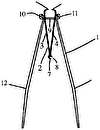
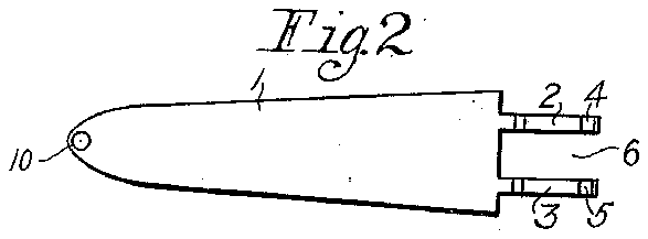
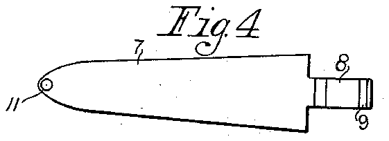
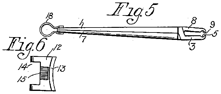
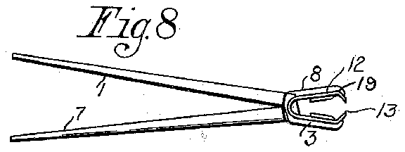
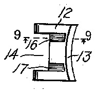
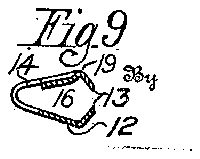
The invention includes the three separable parts illustrated in the accompanying drawings, of which Fig. 1 represents a side view of one of the jaws, and Fig. 2 a top view thereof looking at the flat side or face of the jaw. Fig. 3 is a side view of the complementary jaw and Fig. 4 is a bottom or flat face view of the jaw. Fig. 5 is a side View of the two jaws in engagement without the spring. Fig. 6 is a top view of the V-shaped spring, and Fig. 7 is a bottom view thereof. Fig. 8 is a side view of all the parts assembled. Fig. 9 is a sectional view of the cutter spring taken upon the broken line 99 of Fig. 7.
'The scale of drawing is double the actual size of this invention to render the construction clearer, and throughout the drawings and description the same number is used to refer to the same part.
Considering the drawings, the jaw 1 has the offset projections 2 and 8 provided near their extremities with the small transverse grooves 4t and 5. Between the projections is a space marked 6.
Figs. 3 and 4 illustrate the second jaw 7 having a single offset projection at the jaw end provided with the transverse groove 9.
By introducing the single projection 8 of jaw 7 into the space 6 of the end of jaw 1, the two jaws may be associated as illustrated in Fig. 5. The jaws may be provided with small holes 10 and 11 at their free ends, intended to engage a clip or key-ring as shown in Fig. 5, and which will hold the jaws together.
In Figs. (3 and 7 and 9 the Vshaped cutter spring is referred to as a whole by the number 12. The spring has a curving cutting edge 13, and a recess 14 in its rear. On one side or face of the spring is formed a single depression 15, and on the other face the two spaced depressions 16 and 17. In Fig. 9 it will be noted that the cutting edges 13 slant towards each other, and that by reason of the formation of the depression 16 and the other depressions a ridge or shoulder 19 is formed between the depression and the cutting edge. In assembling the parts the project-ions 2 and 3 of jaw 1 engage the spaced depressions 16 and 17, and the ridges between those projections and the cutting edge of the spring enter grooves at and 5. Similarly the projection 8 seats itself in depression 15, and the adjacent ridge engages groove 9/ In operation, if the jaws are opened as shown in Fig. 8 the spring 12 may be positioned or removed by bringing its cutting edges together with the fingers, no tool being called for.
The clasp or key-ring 18 may be of any selected pattern, and the clip as a whole, usually ornamental in design externally, may be carried attached to a watch chain or the like.
It will now be understood that only three parts are required. to complete this invention, that it has no pivot pin or rivet, and that the parts are freely detachable and as easily assembled, resulting in a very effective and convenient clip for cutting the finger nails.
Having now described this invention and explained the manner of its operation, I claim:
1. A nail clip, comprising separable jaws provided at the ends with oppositely oflset projections, the said projections being constructed to engage each other leaving a space between the jaw ends, each of the said projections having a transverse groove near its extremity, and a cutter spring located in the said space and having ridges arranged in engagement with the said grooves of the projections whereby the jaws are maintained in engagement against displacement in the direction of the length of said jaws and the said spring is held in operative relation to the jaws and against displacement therefrom.
2. A nail clip comprising jaws separable bodily, one of said jaws having at its end a portion formed into a pair of spaced offset projections, a second jaw having a single off-set projection passing between the said spaced projections of the first aw, the projections of both jaws having transverse grooves at their extremities, and a cutter spring having a rear recess receiving and engaging the outer sides of the said pair of projections of the first jaw whereby the spring is held against displacement sidewise, the said cutter spring being located between the said projections of the jaws as shown and constructed and arranged to engage the said grooved ends of the said projections, the expansion of the said spring acting to keep the jaws together in operative relation and prevent relative displacement of said jaws in the direction of the length of the jaws.
In testimony whereof I aflix my signature.
MAX SCHNEFEL.

