

- 1said
- 5lines
- 9on 3462 v y :f melvin ff hanson get.v
- 22pivot
- 23le
- 30spaced locking lugs
- 31ted together :with 'the nail cutters
- 32ted together :with 'the nail cutters
- 33attaching screws
- 34blade
- 35cutters
- 36headed positioning studs
- 37headed positioning studs
Description
Oct. 9, 1934. M E HANSON 1,976,067'
SAFETY MANICURING AND FINGER NAIL CUTTER COMBINATION 3462 v y :f
Melvin Ff Hanson Get.v 9, 1934. M' F, HANSON l 1,976,067
SAFETY MANICURING AND FINGER NAIL CUTTER COMBINATION Filed Dec. 30; 1933 2 Sheets-Sheet 2 345 f, @ad
34a a4 31a 35d 35a 3B ,T72 ve 2'? for me Zvin H @715011 Patented Oct. 9, 1934 SAFETY MANTcUnnvG AND FINGER NAIL l CUTTER COMBINATION Melvin li'. Hanson, Boston, Mass.; assignor to Morris Moshin, Boston, Masa Application December so, 1933, serial No. '104,664
4 claims. (o1. so-es) 'lhis invention relates to manicuring implements, and particularly to an implement combining in a single unit the functions of a cuticle cutter and a nail cutter.
i Objects of the invention are toprovide a com bination implement for performing the above functions which will be extremely simple in construction and unusually efficient in operation; which will he capable of commercial manufacture at low cost; which will cut with equal facility either the cuticle orV the nails; which when used as a cuticle cutter will trim the cuticle without danger of cutting too deeply into the cuticle; and nally which will provide the maximum leverage with the of weight and size so as to venable it conveniently to be carried in the pocket or the purse. i
These objects, together with certain other structural and operational advantages which r will appear more fully hereinafter, are attained,V
in the device of the present invention.
ln the accompanying drawings, I showV one structural embodiment of Ymy invention which I have found highly satisfactory in actual service and well adapted to the requirements of commercial manufacture.
Such embodiment may be taken as typical of the principles involved, although it will he understood that it is selected as illustrative only and that my invention is capable of various modifica.- tions in structure and design.
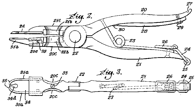
Figs. l, 2 and3 are top, side, and bottom views, respectively, of a manicure implement in accordance with my'invention. Y
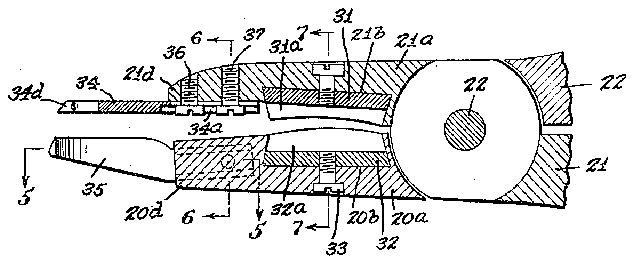
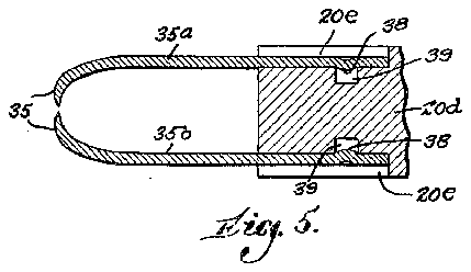
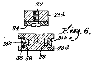
Fig. 4 is an enlarged section on the line i-4Y liigs. 5, 6 and 'l are sections on the lines 5 5,
26 of said latch is adapted to lock Within a S1013 Y 2'1 at the extremity ofthe other handle. Obviously, of course, other forms of locking device 'may be used, or the locking dev ice may be entirely omitted rif desired. Y A If desired, a nail'file and cleaner 28 may be pivoted, as at 29, `to the under face of one of the handles. When not in use, the le 23 may be locked in an out-of-the-way position against the under face of the handle to which it is pivoted.
This may be conveniently accomplished by forming the under face of the handle with a pair of spaced locking lugs 30 between which the pointed end of the tile 28 is adapted to be frictionally lodged.
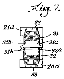
Beyond the pivot 22 the handles extend as op- 65 posing jaws 26a and 21a. The inner faces of these jawsare oppositely recessed from sideY to side, as indicated at 2Gb and 2lb to provide sockets within which a pair of coacting nail out# ters 3l and 32 are removably mounted.
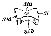
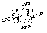
, Each cutter presents right and left hand cutting blades 31a and 31h, and 32a and 32h, respectively, the opposing edges of which are sharp- `ened for coaction with each other when the jaws are closed towards each other.
Preferably the respective cutter blades of each cutter are oppositely curved as at 31e and 32e to correspond substantially to the normal curvature of the linger nails of the right and left hands.
Preferably, also, the lateral faces of the jaws beyond the recesses thereof are laterally cut away as indicated at 20c and 21e to permit the nail to be conveniently inserted between one or the other of the pairs of the opposing cutter blades, accordingly as to whether the implement is beingA usedtoV cut the nails of the'right or left hand.
The cutters themselves may be of any desired construction. -Preferably they are detachable so 1 that they may be removed from their mounting sockets and sharpened or replaced b y new cutter units when dulled. 'd
Y Preferably also each cutter is constructed as a unit (see Figs. 10 and 13) in the form of a die or block presenting a base 31d or 32d bottoming on the mounting sockets. From said bases rise the blades 31a. 3lb or 32a and 32h.
These cutter units maybe detachably but securely retained in their mounting sockets in any-A desired manner. Their frictional fit within the sockets may be sufficiently Ytight to accomplish 1m;
this, or the units may be positively fastened, as
by means of attaching screws 33 or thelike set i ilush within the jaws. f Beyond the cutters, the jaws extend as sup porting surfaces 20d and 21d fora pair of oppos- 105 lng cuticle cutters 34 and 35 *which are preferably detachably mounted thereon.
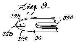
The cutter 34 is a flat blade mounted on the inner surface -of the :iaw extremity 21d in any suitable manner and extending axially therebe- 11b yond.' Preferably, the inner end of the blade-34 is longitudinally slotted as indicated. at 34a. to slide over a pair of headed positioning studs 36 and 37 fixed to the inner face of said jaw extremity. (See Fig. 4.)
Beyond-said .jaw extremity, the blade 34 extends as a combination guard and cutter. The
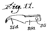
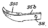
. lateral edges' of such cutter are curved inwardlytowards eachother and sharpened as indicatedat 34h and 34e, being separated from each other by a rie-entrant slot 34d disposed substantially centrally of the outer end of the blade. (See Fig. 9.) Thus the outer end of the blade 34 presents a pair of oppositely curved cutting surfaces 34b and 34e. ,These constitute right and left hand cutting edges adapted for coactionwith the similarly curved cutting surfaces of the opposite cuticle cutter' 35. The cutter 35 is formed as apair of blade elements 35a and 35h. (See Figs. 11 and 12.) These extend back into the jaw extremity 20d, said extremity being slotted as at 20e to receive the blades and the blades being detachably mounted Beyond the jaw extremity 20d the blades 35a and 35b are curved inwardly towards each other` on arcs of slightly larger-radius than thecurvature of the cuttingblades 34h and-34e of the vcoacting. cutter 34.
When the jaws are pressed towards each other,
theblades 35a and 35h travel past the blades 4341i and 34e, outwardly thereof, to effect a shearing cut, the adjacent edges of the blades 35a and 35h being-sharpened as at 35C and 35d to coact with the sharpened lateral edges of the blades 34h and rn assembling the imp1ement,uie handles are pi-voted together :with 'the nail cutters 31 and 32 mounted in their receiving'sockets, and the cuticl cutters 34 and 35 mounted on the jaw extremities inthe relation described.
In operating the implement as a nail cutter, the opposing cutting blades3la and 32a at the left side of the implement would naturally be used to cut the left handnails if the implement were '-held in the-right hand, and the -opposing blades would naturally be used to cut the right hand nails if the implement were held in the left hand.
In operating the implement a cuticle cutter, one side edge of the atcutter blade 34 is inserted under the cuticle.` When the jaws are pressed together, the'sharpened edges 35o and 35d of the cutter blades 35a and' 35h travel past the beveled side edges- 34h and 34e to produce shearing cuts.
. If the instrument be held in the right hand to cut the cuticle of the left hand, the cooperating cutting edges 3411 and 35e effectively coact as a shear. -If theinstrument is held in the left hand,
cutting edges 34h and 35e and 34e and 35d past each other tends to make these blades self-sharpening to some extent inaction.
On account of the construction and manner of or shearing action of the mounting the nail and cuticle cutter blades, it is 4`possible to cut nails .and/or cuticle onany desired tachable and replaceable, -it is within the purview i of my invention to furnish with each implement one or more extra sets of cutters as replacements.
Although I have described my manicure implement as a combination nail and cuticle cutter it may obviously be used for other purposes, as in certain surgical uses, or for cutting corns. callouses'etc.
Similarly, I recognize that many variations in structural and functional details are possible. All such are to be regarded as included .within the spirit and scope of myinvenltion, if within the limits of the appended claims.
What I therefore claim and desire to secure by Letters Patent is:'
1'. A manicuring implement, comprising a pair of crossed pivoted handles providing spaced jaws terminating in mounting portions, a pair of op-- Posing cuticle cutters mounted on said jaw terminals, one of said cuticle cutters consisting of a relatively flatsingle blade, having itslateral edges l curved towards each other and sharpened to provide a pair of cutting edges, the coacting cuticle cutter comprising a pair'of spaced blades the rear vendsof which extend along either side of the longitudinal axis of the jaw terminal on which said 1 blade pair is mounted, the forward ends of said pair of blades being curved towards each other and having their. edges opposite the single blade sharpened, and the arcs of curvature on which the pair of blades were developed being greater l than those on which the lateral cutting edges of the single blade were developed so that the sharpened edges of the pair of blades pass outside of the sharpened lateral edges of the single blade and produce a shearing cut between said coactl ing cutting edges.
2. A manicuring' implement as claimed in claim l wherein the'jaw terminal on which the pair of blades is mounted is longitudinally slotted at either side o f its central median line to receive l the rear ends of said pair of blades-andis also provided with a pair of locking recesses and whereinathe rear ends of said blades are formed with indentations adapted to enter and be frictionally retained within said locking recesses. 1
3. A manicuring implement, comprising a pair of crossed pivoted handles providing spaced jaws terminating in mounting portions,- a pair of opposing VAcuticle cutters mmmted on said jaw terminals, one of said cuticle cutters consisting of a 1 relatively flat single blade, the rear end of which overlaps theinner face of its jaw terminal and has a longitudinal slot,l a headed fastening exnding through said jaw terminal with its head disposed in said slot for adjustably and detach- 1 ably' fastening said blade -to saidterminal, said-- blade beyond said terminal having its lateral edges curved towards each other and sharpened to provide a pair of cutting edges, and having at its forward end' an axial slot separating said 1 rounded cutting edges, thecoacting cuticle eutter comprising a pair of spaced blades the rear ends of which extend rearwardly of the opposite jaw Vterminal at .either sideof the longitudinal axis thereof, said pair of blades beyond said terl minal being curved towards each other and having their edges 'opposite the single'.blade sharpened, and the arcs of curvature on which the pair of blades were developed being greater than those on which the lateral cutting edges of the single 1 at either side of its central median line to receive the rear ends of said pair of blades and is also provided with a pair of locking recesses and wherein the rear ends of sazid blades are formed with indentatons adapted bo enter and be frictionally retained said 'locking recesses.
lViELVIN F. HANSON.

