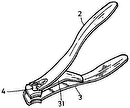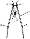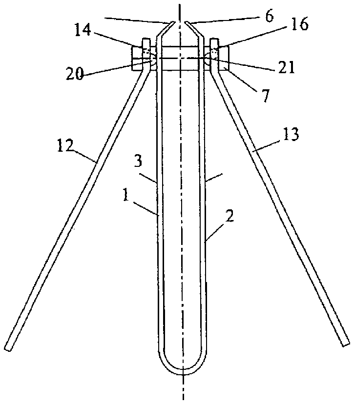
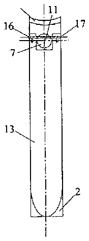
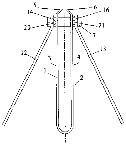
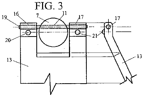
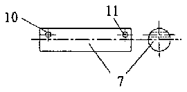
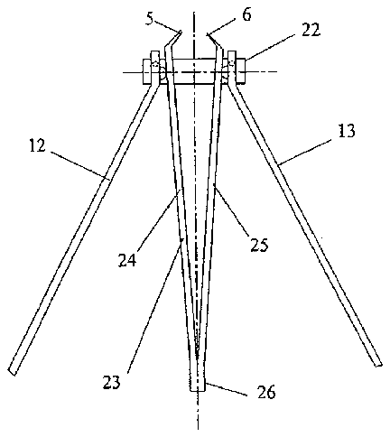
- 1nail clipper
- 2pincer member
- 3jaws
- 5sharp cutting edges
- 6sharp cutting edges
- 7transverse assembling pin
- 10symmetrical bores
- 11bore
- 12handles
- 13handle
- 14bores
- 16bores
- 17bore
- 18corresponding small diameter steel wire
- 19small diameter steel wire or rod
- 20cam-like protrusions
- 21cam-like small protrusion
- 22nail clipper
- 23central pincer member
- 24jaw members
- 26closed end
- 28fulcrum point
- 35under
Abstract
A nail clipper includes a pincer forming multiple opposed sections. A first opposed section includes a first jaw spaced from a second jaw of a second opposed section. The nail clipper also includes a transverse assembling pin mounted between the opposed sections of the pincer. At least one handle is provided. The at least one handle includes a short portion and a long portion. The short portion is mounted to the transverse assembling pin such that a fulcrum point of the handle on the transverse assembling pin remains at substantially a cross-sectional center of the transverse assembling pin when the at least one handle is rotated relative to the pincer.
Description
CROSS-REFERENCE TO RELATED APPLICATIONS
[0001] This application claims the benefits, under 35 U.S.C. §119(e), of U.S. Provisional Application No. 60/651,213, filed Feb. 10, 2005, the subject matter of which is incorporated by reference in its entirety.
BACKGROUND OF THE DISCLOSURE
[0002] 1. Field of the Disclosure
[0003] The present disclosure relates to nail clippers. More particularly, the present disclosure relates to nail clippers that distribute cutting force at cutting edges.
[0004] 2. Background Information
[0005] U.S. Pat. No. 6,173,497 is directed to a nail clipper which includes a central symmetrical resilient pincer member with cutting edges at an open end. The nail clipper also includes a transverse pin with hooked ends that pass through opposed and aligned bores on the jaws of the pincer member near the open end. Twin lateral handles are connected at the hooked end of the transverse pin, and remain aligned at all positions. The configuration of U.S. Pat. No. 6,173,497 allows a user to change a relative angle between the pincer member and the twin lateral handles. A cutting stroke can be performed at practically any angle between the pincer member and the lateral handles.
[0006] The configuration of U.S. Pat. No. 6,173,497 provides both an increased mechanical advantage and improved ergonomic characteristics for the nail clippers disclosed therein. However, according to the configuration of U.S. Pat. No. 6,173,497, when the handles are angled with respect to a pincer member, e.g., at 90 degrees, a resistance point is positioned near the lateral edge of the pincer members. As a result, an opposed pressing force is applied to the handles during the cutting stroke, and the cutting stroke is not evenly distributed.
BRIEF DESCRIPTION OF THE DRAWINGS
[0007] The present disclosure is further described in the detailed description that follows, by reference to the noted drawings by way of non-limiting examples of embodiments of the present disclosure, in which like reference numerals represent similar parts throughout several views of the drawing, and in which:
[0008] FIG. 1 shows a side elevation view of an exemplary nail clipper according to a first embodiment of the present disclosure;
[0009] FIG. 2 shows a top elevation view of the exemplary nail clipper according to the first embodiment shown in FIG. 1 ;
[0010] FIG. 3 shows a top elevation view of an exemplary handle and exemplary transverse assembling pin;
[0011] FIG. 4 shows a side elevation view of the exemplary handle shown in FIG. 3 ;
[0012] FIG. 5 shows a side elevation view of an exemplary transverse assembling pin;
[0013] FIG. 6 shows an end view of the exemplary transverse assembling pin shown in FIG. 5 ;
[0014] FIG. 7 shows a side elevation view of an exemplary small diameter wire;
[0015] FIG. 8 shows an end view of the exemplary small diameter wire shown in FIG. 7 ; and
[0016] FIG. 9 shows a side elevation view of an exemplary nail clipper according to a second embodiment of the present disclosure;
[0017] FIGS. 10A and 10B show front and top elevation views of an exemplary nail clipper, with handles deployed at a 90 degree angle relative to a pincer member, according to the second embodiment shown in FIG. 9 ;
[0018] FIG. 11 shows a side elevation view of an exemplary nail clipper according to a third embodiment of the present disclosure;
[0019] FIG. 12 shows a top elevation view of the exemplary nail clippers according to the third embodiment shown in FIG. 11 ;
[0020] FIG. 13 shows a top elevation view of an exemplary handle and exemplary transverse assembling pin of the exemplary nail clippers according to the third embodiment shown in FIG. 11 ; and
[0021] FIG. 14 shows a side elevation view of the exemplary handle of the third embodiment shown in FIG. 13 .
DETAILED DESCRIPTION
[0022] In view of the foregoing, the present disclosure, through one or more of its various aspects, embodiments and/or specific features or sub-components, is thus intended to bring out one or more of the advantages as specifically noted below.
[0023] In order to improve the distribution of cutting force along cutting edges, nail clippers as disclosed in exemplary embodiments herein are provided with a resistance point positioned at or near the longitudinal center of the handles.
[0024] According to an aspect of the present disclosure, a nail clipper includes a pincer forming multiple opposed sections, a first opposed section including a first jaw spaced from a second jaw of a second opposed section. The nail clipper also includes a transverse assembling pin mounted between the opposed sections of the pincer. The nail clipper further includes at least one handle including a short portion and a long portion. The short portion is mounted to the transverse assembling pin such that a fulcrum point of the handle on the transverse assembling pin remains at substantially a cross-sectional center of the transverse assembling pin when the at least one handle is rotated relative to the pincer.
[0025] According to another aspect of the present disclosure, a profile of the opposed sections of the pincer substantially forms a generally U-shape and the jaws partially enclose an open end of the U-shape.
[0026] According to still another aspect of the present disclosure, a profile of the opposed sections of the pincer substantially forms a generally V-shape and the jaws partially enclose an open end of the V-shape.
[0027] According to yet another aspect of the present disclosure, the short portion of each at least one handle includes at least one cam-like protrusion which contacts the pincer.
[0028] According to another aspect of the present disclosure, the cam-like protrusion is semi-spherical.
[0029] According to still another aspect of the present disclosure, the at least one cam-like protrusion of the short portion of each at least one handle includes two cam-like protrusions.
[0030] According to yet another aspect of the present disclosure, the short portion of each at least one handle substantially forms a generally U-shape that is fitted around the transverse assembling pin.
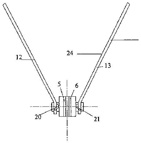
[0031] According to an aspect of the present disclosure, a nail clipper includes a pincer forming a plurality of opposed sections, a first opposed section including a first jaw spaced from a second jaw of a second opposed section. The nail clipper also includes a transverse assembling pin mounted between the opposed sections of the pincer. The nail clipper further includes two handles, each including a short portion and a long portion, and each handle being mounted to the transverse assembling pin such that contact between each handle and the transverse assembling pin remains at substantially a cross-sectional center of the transverse assembling pin when the at least one handle is rotated relative to the pincer.
[0032] According to another aspect of the present disclosure, the contact between each handle and the transverse assembling pin occurs at a line of intersection between the short portion and the long portion.
[0033] According to still another aspect of the present disclosure, the opposed sections of the pincer comprise two equal and opposed jaw members which are rigidly connected at a closed end.
[0034] According to yet another aspect of the present disclosure, the opposed sections are rigidly connected by welding.
[0035] According to another aspect of the present disclosure, the opposed sections are rigidly connected by riveting.
[0036] According to still another aspect of the present disclosure, the short portion of each at least one handle includes at least two cam-like protrusions which contact the pincer and upon which each handle pivots when operated to move one of the first jaw and the second jaw towards the other of the first jaw and the second jaw to exert a cutting force.
[0037] According to yet another aspect of the present disclosure, the short portion of each handle forms a generally U-shape that is fitted around the transverse assembling pin, and the assembling pin rotates with a rotation of the two handles:
[0038] According to an aspect of the present disclosure, a nail clipper includes a pincer forming a plurality of opposed sections, a first opposed section including a first jaw spaced from a second jaw of a second opposed section. The nail clipper also includes a transverse assembling pin mounted between the opposed sections of the pincer. The nail clipper further includes two handles, each mounted to the transverse assembling pin by at least one connector passed through at least one bore of each handle and at least one bore of the transverse assembling pin.
[0039] According to another aspect of the present disclosure, the transverse assembling pin comprises symmetrical bores at opposed ends through which connectors are respectively passed through to mount the handles to the transverse assembling pin.
[0040] According to still another aspect of the present disclosure, the short portion of each handle forms a generally U-shape and two opposing sections of the U-shape comprise symmetrical bores through which a connector is respectively passed to mount the handles to the transverse assembling pin.
[0041] According to yet another aspect of the present disclosure, the transverse assembling pin comprises symmetrical bores at opposed ends through which connectors are respectively passed. The short portion of each handle forms a generally U-shape and two opposing sections of the U-shape comprise symmetrical bores through which a connector is respectively passed. The bore at a respective end of the transverse assembling pin is aligned with the symmetrical bores of a respective section of the U-shaped short portion of the handle.
[0042] According to another aspect of the present disclosure, a connector is passed through the aligned bore at an end of the transverse assembling pin and the symmetrical bores of a section of the U-shaped short portion of the handle, the wire serving as an axle for mounting the handle to the transverse assembling pin.
[0043] According to yet another aspect of the present disclosure, the connector comprises one of a wire and a rod.
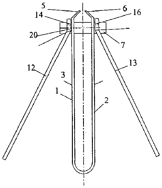
[0044] FIG. 1 illustrates a side elevation view of a nail clipper 1 with a generally “U” shaped resilient central pincer member 2 . As shown, the pincer member 2 has symmetrical first and second jaws 3 , 4 respectively terminating in opposing sharp cutting edges 5 , 6 . The resilient central pincer member 2 is formed generally in a U-shape, with an open end of the “U” partially closed by the opposed sections of the sharp cutting edges 5 , 6 . The sharp cutting edges 5 , 6 may be formed to have any suitable shape to perform a cutting function, such as the curved shape shown in FIG. 2 . Two handles 12 , 13 are respectively mounted to the pincer member 2 via a transverse assembling pin 7 . The transverse assembling pin 7 is disposed in apertures (not shown) in jaws 3 , 4 . The handles each include a short portion and a long portion. The apertures in jaws 3 , 4 are disposed towards the open end of the “U” formed by the central resilient pincer member 2 , and the transverse assembling pin is disposed in the apertures near where the sharp cutting edges 5 , 6 partially close the open end of the “U”. The apertures are of a size sufficient to allow rotation of the transverse assembling pin 7 .
[0045] Cam-like protrusions 20 , 21 provide fulcrum points on which the handles 12 , 13 are squeezed towards each other in order to exert a cutting force between the cutting edges 5 , 6 . The cam-like protrusions 20 , 21 are provided on the short portions of the handles 12 , 13 , shown as the uppermost portion of the handles 12 , 13 in FIG. 1 . A user grips the handles 12 , 13 on the long portions thereof to apply a pressing force to the jaws 3 , 4 .
[0046] Although the fulcrum points are shown as single (individual) protrusions 20 , 21 on each handle 12 , 13 in FIG. 1 , the fulcrums may be more than a single (individual) protrusion on the handle. For example, the top elevation view of FIG. 3 shows two protrusions 20 , 21 on each opposite leg of a single generally U-shaped short section of the handle 13 .
[0047] As shown in FIG. 1 , the handles 12 , 13 are fixed to the pincer at the short portions. The generally U-shaped short portions of handles 12 , 13 are provided at ends with small diameter bores (three bores 14 , 16 , 17 being shown in FIGS. 1-4 ). As explained below and illustrated in FIGS. 2-3 , the small diameter bores are aligned with eccentric bores 10 , 11 respectively of the transverse assembling pin 7 .
[0048] FIG. 2 illustrates the nail clipper 1 shown in FIG. 1 as viewed from the top. As shown, two small diameter bores 16 , 17 are provided in the opposing legs of the U-shaped short section of the handle 13 . When viewed from the top, the two small diameter bores 16 , 17 are aligned with the bore 11 in the transverse assembling pin 7 .
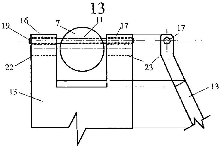
[0049] The set of small diameter bores 11 , 16 , 17 are also shown in FIG. 3 . As shown in FIG. 3 , the small diameter bores 11 , 16 , 17 are aligned coaxially. A small diameter steel wire or rod 19 is passed through bores 11 , 16 , 17 . Although not shown in detail, a small diameter steel wire or rod is passed through the set of bores (including bore 14 shown in FIG. 1 ) which are aligned coaxially along the transverse assembling pin 7 and along the opposing legs of a U-shaped short section of the handle 12 . A bore corresponding to bore 11 is provided in the transverse assembling pin 7 opposite of the side which includes bore 11 . As shown in FIG. 3 , the handle 13 is rotatably mounted to the small diameter wire or rod 19 . Additionally, although not shown, the handle 12 is rotatably mounted to the small diameter wire or rod corresponding to wire or rod 19 . The handles 12 , 13 are provided with lateral perforations at their open (gripping) ends.
[0050] Handles 12 , 13 are further provided in the inner part of the short portion at the non-gripping end with cam-like protrusions 20 , 21 . In an embodiment, the cam-like protrusions 20 , 21 are generally semi-spherical. If a single cam-like protrusion is provided for each handle, the fulcrum for the handle is at the cam-like protrusion. However, if two cam-like protrusions 20 , 21 are provided for each handle, the fulcrum point is along a line segment connecting centers of the cam-like protrusions 20 , 21 . As explained below with respect to FIG. 3 , the fulcrum point between two cam-like protrusions 20 , 21 is positioned along a line segment which includes a center of the circle formed by the cross-section of cylindrical assembling pin 7 . Furthermore, although the cam-like protrusions 20 , 21 are shown to be generally semi-spherical, the protrusions may be formed to have any suitable shape that will provide a camming function.
[0051] FIG. 3 is a generally top view of handle 13 . Although not illustrated in FIG. 3 , the handle 12 is symmetric to the handle 13 and includes similar features. The small diameter wire 19 is passed through bore 16 of the handle 13 , bore 11 of the transverse assembling pin 7 and bore 17 of the handle 13 .
[0052] The exemplary embodiment shown in FIG. 3 includes a transverse assembling pin 7 . The transverse assembling pin 7 has a generally circular cross-section and a somewhat larger diameter relative to a conventional nail clipper. However, the transverse assembling pin 7 may have any suitable shape. The transverse assembling pin 7 is provided at one end with an eccentric small bore 11 to form a chord. The transverse assembling pin 7 is provided at its other end (shown in FIG. 5 ) with another eccentric small bore 10 to form another chord. The small wire or rod 19 is passed through bores 16 , 17 of the handle 13 and the transverse pin eccentric bore 11 . The small diameter wire 19 serves as an axle, and replaces the hooked articulation arrangement between the handles and the transverse assembling pin of U.S. Pat. No. 6,173,497. Although not shown in FIG. 3 , another small wire is passed through the corresponding bores of the handle 12 and the transverse pin eccentric bore 10 .
[0053] In an embodiment, the improved nail clippers are manufactured using any suitable material, for example high quality templated stainless steel.
[0054] FIG. 4 is a side elevation view of the handle 13 . As shown, the handle 13 includes the bore 17 through the short section of the handle 13 . The side elevation view of the handle 13 also shows a profile of the cam-like small protrusion 21 on the short section of the handle 13 .
[0055] FIG. 5 illustrates an exemplary transverse assembling pin 7 . As shown in FIG. 5 , the transverse assembling pin 7 is provided at opposite ends with two eccentric small diameter distal and symmetrical bores 10 , 11 . The small diameter distal and symmetrical bores 10 , 11 are offset from the central longitudinal axis of the assembling pin 7 and form chords with respect to a circular cross section of the transverse assembling pin 7 . As described and shown with respect to FIG. 3 , the bore 11 of the transverse assembling pin 7 is aligned with the bores 16 , 17 of the U-shaped short section of the handle 13 . Further, although not shown in FIG. 3 , the bore 10 of the transverse assembling pin 7 is aligned with the corresponding bores of the U-shaped short section of the handle 12 .
[0056] FIG. 5 also shows that a center of the symmetrical bores 10 , 111 is offset from a center of the transverse assembling pin 7 . This arrangement is also shown in the top view of FIG. 3 by bore 11 . On the other hand, a line segment that connects the center of the protrusions 20 , 21 on the U-shaped short section of the handle 13 passes through a cross-sectional center of the transverse assembling pin 7 . As a result, regardless of the rotation of the handles 12 , 13 and the transverse assembling pin 7 , a central fulcrum point of the handles 12 , 13 is placed at or near the center of the assembling pin 7 . Accordingly, a cutting force of the cutting edges 5 , 6 is more evenly distributed along the cutting edges 5 , 6 when the handles 12 , 13 and the transverse assembling pin 7 are rotated and the handles 12 , 13 are squeezed together. This distribution of the cutting force is improved in comparison to when the fulcrum upon which the handles 12 , 13 are levered is placed near the edge of the pincer 2 by rotation of the handles 12 , 13 and the transverse assembling pin 7 . Of course, the handles 12 , 13 may be leveraged by more than two protrusions 20 , 21 on each U-shaped short section of the handles 12 , 13 , in which the fulcrum will depend on the relative placement of the protrusions.
[0057] FIG. 6 shows an end view of assembling pin 7 in isolation.
[0058] FIG. 7 is a view of small diameter steel wire or rod 19 , and FIG. 8 is an end view of the small diameter steel wire or rod 19 (which is the same as the corresponding small diameter steel wire or rod provided for handle 12 ). The small diameter steel wire or rod 19 through bores 16 , 11 , 17 serves as an axle on which handle 13 is rotatably mounted. A corresponding small diameter steel wire 18 through corresponding bores 14 , 10 , 15 serves as an axle on which handle 12 is rotatably mounted.
[0059] FIG. 9 is a side elevation view of a second embodiment of the present disclosure. As shown, a nail clipper 22 includes a central pincer member 23 composed of two substantially equal and opposed jaw members 24 , 25 . The jaw members 24 , 25 are rigidly connected at a closed end 26 . The connection of jaw members 24 , 25 may be accomplished in any suitable manner, e.g., by welding or rivets. As shown, the central pincer member 23 is generally formed in a V-shape, with an open end of the “V” partially closed by the opposed sections of the sharp cutting edges 5 , 6 . The sharp cutting edges 5 , 6 may have any suitable shape to perform a cutting function.
[0060] FIGS. 10A and 10B are a front elevation view and a top elevation view of nail clipper 22 according to the second embodiment. As shown, the nail clipper 22 includes handles 12 , 13 deployed at a 90 degree angle with respect to the jaws pincer 2 , 23 . Small protrusions 20 , 21 make contact with the lateral jaws along the prolongation line of the pin 7 . As shown in the top elevation view of FIG. 10B , the fulcrum along the line segment between the small protrusions 20 , 21 is consistently centered at or near the cross sectional center of the transverse assembling pin 7 even when the handles and the transverse assembling pin are rotated by 90 degrees. This allows a more even distribution of the squeezing force of the jaws, which in turn permits a more even distribution of the cutting force along the cutting edges 5 , 6 .
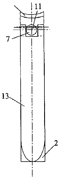
[0061] FIGS. 11-14 show a third embodiment of the present disclosure. As shown, a nail clipper 1 is similar to the nail clipper 1 in the first embodiment. However, the nail clipper 1 in FIGS. 11-14 is not provided with the cam-like semi-spherical protrusions 20 , 21 of the first embodiment. Rather, in the third embodiment, the fulcrum point 28 , 29 is determined by the bending angles of the short and long portions of the handles 12 , 13 . As shown, a fulcrum point 28 , 29 of the nail clipper 1 of the third embodiment is placed and maintained at or near the center of the transverse assembling pin 7 . This arrangement permits a substantially even distribution of the cutting force at the cutting edges even when the handles 12 , 13 and the transverse assembling pin 7 are rotated.
[0062] As described above, a nail clipper as disclosed herein includes a handle that is mounted to a transverse assembling pin such that a fulcrum point of the handle on the transverse assembling pin remains at or near (substantially at) a cross-sectional center of the transverse assembling pin when the handle is rotated relative to a pincer of the nail clipper. This permits an even application of a cutting force compared to when a fulcrum point of the handle on the transverse assembling pin is positioned near the edge of a pincer member, such as when the handles and a transverse assembling pin are rotated relative to the pincer member.
[0063] The illustrations of the embodiments described herein are intended to provide a general understanding of the structure of the various embodiments. The illustrations are not intended to serve as a complete description of all of the elements and features of apparatus and systems that utilize the structures or methods described herein. Many other embodiments may be apparent to those of skill in the art upon reviewing the disclosure. Other embodiments may be utilized and derived from the disclosure, such that structural and logical substitutions and changes may be made without departing from the scope of the disclosure. Additionally, the illustrations are merely representational and may not be drawn to scale. Certain proportions within the illustrations may be exaggerated, while other proportions may be minimized. Accordingly, the disclosure and the figures are to be regarded as illustrative rather than restrictive.
[0064] One or more embodiments of the disclosure may be referred to herein, individually and/or collectively, by the term “invention” merely for convenience and without intending to voluntarily limit the scope of this application to any particular invention or inventive concept. Moreover, although specific embodiments have been illustrated and described herein, it should be appreciated that any subsequent arrangement designed to achieve the same or similar purpose may be substituted for the specific embodiments shown. This disclosure is intended to cover any and all subsequent adaptations or variations of various embodiments. Combinations of the above embodiments, and other embodiments not specifically described herein, will be apparent to those of skill in the art upon reviewing the description.
[0065] The Abstract of the Disclosure is provided to comply with 37 C.F.R. §1.72(b) and is submitted with the understanding that it will not be used to interpret or limit the scope or meaning of the claims. In addition, in the foregoing Detailed Description, various features may be grouped together or described in a single embodiment for the purpose of streamlining the disclosure. This disclosure is not to be interpreted as reflecting an intention that the claimed embodiments require more features than are expressly recited in each claim. Rather, as the following claims reflect, inventive subject matter may be directed to less than all of the features of any of the disclosed embodiments. Thus, the following claims are incorporated into the Detailed Description, with each claim standing on its own as defining separately claimed subject matter.
[0066] The above disclosed subject matter is to be considered illustrative, and not restrictive, and the appended claims are intended to cover all such modifications, enhancements, and other embodiments which fall within the true spirit and scope of the present disclosure. Thus, to the maximum extent allowed by law, the scope of the present invention is to be determined by the broadest permissible interpretation of the following claims and their equivalents, and shall not be restricted or limited by the foregoing detailed description.
[0067] Although the disclosure has been described with reference to several exemplary embodiments, it is understood that the words that have been used are words of description and illustration, rather than words of limitation. Changes may be made within the purview of the appended claims, as presently stated and as amended, without departing from the scope and spirit of the disclosure in its aspects. Although the disclosure has been described with reference to particular means, materials and embodiments, the invention is not intended to be limited to the particulars disclosed; rather, the invention extends to all functionally equivalent structures, methods, and uses such as are within the scope of the appended claims.
