
- 10nail clipper
- 12arms
- 14second arm
- 16lever
- 18proximal end
- 20point
- 22distal end
- 24end face
- 26receptacle
- 30tab
- 32blade
- 34rivet
- 36shank
- 38proximal end
- 40distal end
- 42fulcrum
- 44tab
- 50cutting edge portion
Abstract
A disposable nail clipper is disclosed herein. Additionally, a nail clipper with removable, disposable cutting edges is disclosed. Also disclosed are methods for using the nail clipper to clip nails. The disclosed nail clipper includes two body arms and at least one cutting edge portion, which is attached to one body arm. In one embodiment, the body arms and a lever are made of three similarly sized approximately rectangular pieces. Each body arm has a cutting edge portions attached thereto so that the cutting edges oppose each other. Each cutting edge portion is located at a distal end of each body arm. In one embodiment, the cutting edge portion is fixedly secured to the distal end of a body arm. In an alternate embodiment, the cutting edge portion is removably attached to the distal end of the body arm.
Description
TECHNICAL FIELD
[0001] This invention pertains generally to personal grooming devices and more particularly to disposable nail clippers and methods for using the same.
BACKGROUND
[0002] Personal grooming devices, including nail clippers, frequently carry bacteria and other pathogens due to their contact with body tissues. Because bacteria and other pathogens from one person can be harmful to another, it is generally recommended that such devices be restricted to only one user or undergo robust sterilization before being used by another. Such restriction or sterilization, however, is difficult, if not impracticable, in certain environments such as athletic training rooms.
[0003] Nail clippers of the prior art do not address the hygiene issues relating to use by many different persons, and so must be sterilized between uses by different persons if the desired level of hygiene is to be achieved. However, sterilization not only increases the cost of supplies, i.e., sterilization fluids and vessels, but also increases the time delay between uses of the clippers. In addition, sterilization requires personnel time to perform or oversee the sterilization, thus further increasing costs.
[0004] In view of the foregoing, it is desirable to have nail clippers that do not need to be sterilized between uses. One solution is to provide for disposable clippers. Another solution is to provide for clippers that have disposable portions subject to contamination by a user.
SUMMARY OF THE INVENTION
[0005] The presently disclosed nail clipper includes a body comprising at least a first arm and a second arm and at least one cutting edge portion. The arms are linked to each other such that they oppose each other at the location of the cutting edge and contact each other by user operation. The cutting edge is mounted to one of the arms such that it opposes the other arm.
[0006] More particularly, each arm has a proximal and distal end wherein the distal end of at least one of the two arms has formed therein a receptacle adopted to receive a cutting edge portion, which has a generally complementary shape so as to reside either permanently or temporarily, within the receptacle. While the disclosed embodiment locates the cutting edge at the very end of the distal end, such location is not necessary. As described above, it is only necessary that the location for the cutting edge permit it to contact the other arm when the nail clipper is manipulated by the user.
[0007] In one disclosed embodiment, the body has two similarly sized, polymeric arms, each having a proximal end and a distal end with a receptacle for a metal cutting edge portion. Each arm preferably has a slight bend so that it is not planar. The arms are joined to each other at their proximal ends thus forming a “V” shape.
[0008] Depending upon the desired configuration, the disposable embodiment will have the cutting edge portion(s) permanently affixed to the arm(s) while the reusable embodiment will removably locate the cutting edge portion(s) in the receptacle(s).
[0009] With respect to the reusable embodiment, the receptacle formed in each distal end is preferably a groove or slot having a base portion and a neck portion. Each cutting edge has a shaped portion generally complementary to the slot or groove. To permit retention of the cutting edge in the receptacle, the base portion of the slot or groove of the arm and the base portion of the cutting edge shaped portion have wider profiles than the neck portions. In this manner, the cutting edge can be mated with the groove or slot during manufacture, after which it is retained therein in a manner similar to that of a dovetail joint. In an alternate embodiment, the groove or slot extends the entire width of the arm's end, and the cutting edge is mated with the groove or slot by laterally sliding the cutting edge into the groove or slot, after which it is retained therein in a manner similar to a dovetail joint. Alternatively, the cutting edges can define the slots and the distal ends of the arms can form corresponding protrusions. The arms can then be manipulated in a traditional manner such that the cutting edges will be squeezed together, thereby cutting an object, e.g., fingernail or toenail, that is positioned between them.
[0010] As is well known in the art, a lever is preferably located on a stud or shank that links the lever arm to one body arm wherein the second body arm is free to move axially along the stud. The lever arm provides sufficient force to the distal end of the clipper upon user manipulation to cut a nail placed between the cutting edge(s). While the disclosed embodiment relies on the lever arm interacting directly on one of the body arms, it is also contemplated that the lever arm can act directly on the cutting edge, thereby eliminating force transmission through the body arm. By positioning the stud proximate the non-moving body arm, stress inherent therein during use of the clippers can also be reduced. The lever arm can be, of course, used in either the disposable or the reusable embodiment.
[0011] The present invention thus provides for a disposable nail clipper and, alternatively, the removal and replacement of disposable cutting edges of a non-disposable nail clipper. With this invention, different users can each use a new and sterile nail clipper or can use one nail clipper body many times, using new and sterile cutting edges every time. Eliminating the necessity of sterilization between each use results in significant cost and time savings. In addition to these benefits, this invention also enhances the safety and protection of athletes and others who come into contact with them by providing a quick and easy way to ensure short, neatly trimmed nails.
[0012] This summary is provided to introduce a selection of concepts in a simplified form that are further described below in the Detailed Description. This summary is not intended to identify key features of the claimed subject matter, nor is it intended to be used as an aid in determining the scope of the claimed subject matter.
BRIEF DESCRIPTION OF THE DRAWINGS
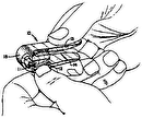
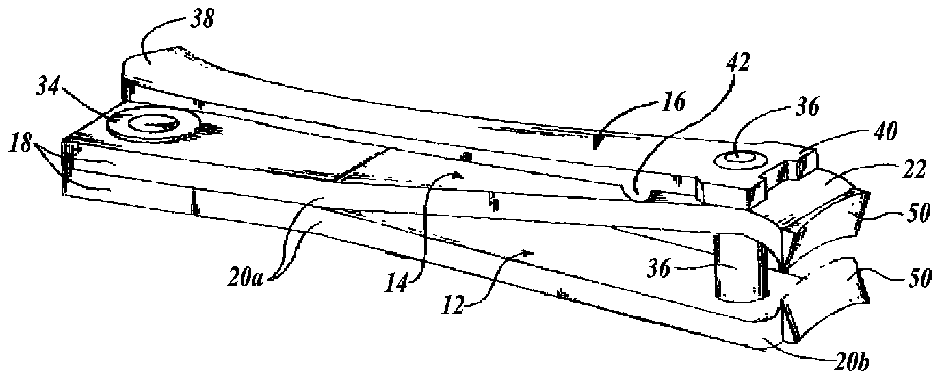
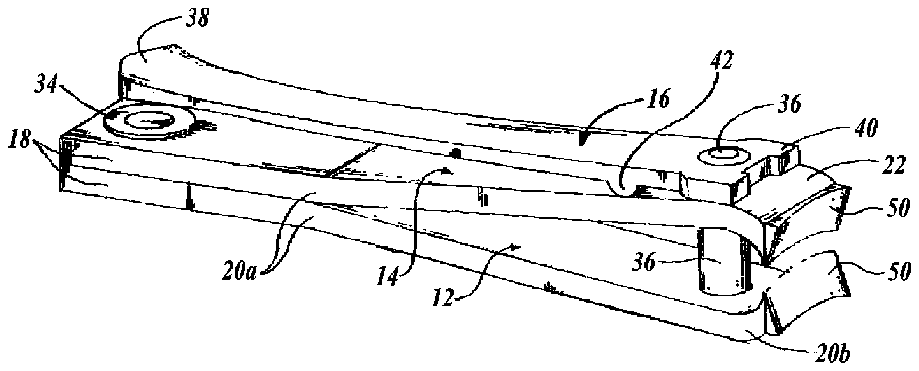
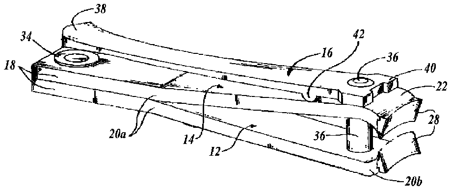
[0013] FIG. 1 is an isometric view of an exemplary embodiment of a nail clipper according to the present disclosure, wherein cutting edge portions are fixedly secured to the body of the nail clipper;
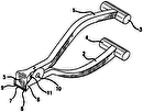
[0014] FIG. 2 is an isometric view of an alternate embodiment of the nail clipper shown in FIG. 1 , wherein cutting edge portions are removably attached to the body of the nail clipper;
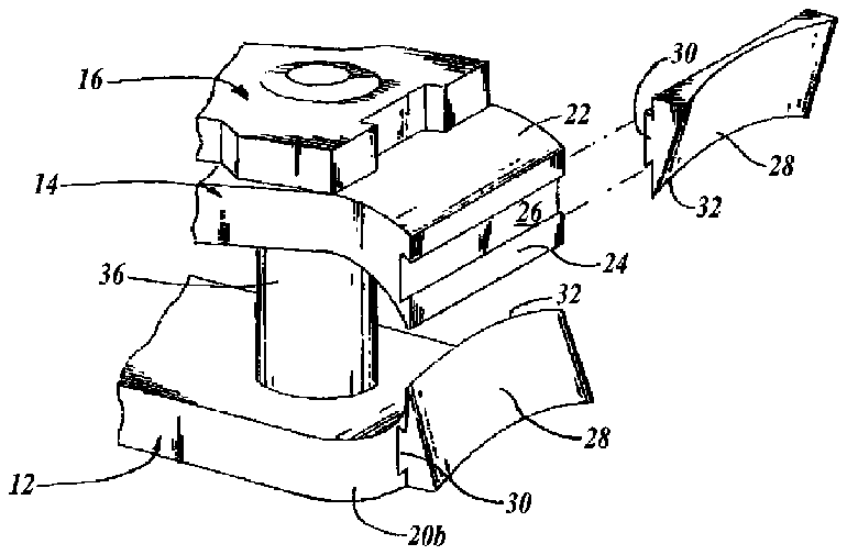
[0015] FIG. 3 is an isometric, exploded partial view of the nail clipper shown in FIG. 2 ;
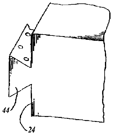
[0016] FIG. 4 is a side view of a second alternate embodiment of the nail clipper shown in FIG. 1 , wherein cutting edge portions are removably attached to the body of the nail clipper; and
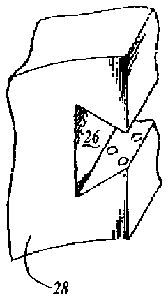
[0017] FIG. 5 is an exploded detail view of an interface of the cutting edge portions and the nail body of the nail clipper shown in FIG. 4 .
DETAILED DESCRIPTION OF THE INVENTION
[0018] Referring to FIG. 1 , an exemplary embodiment of the nail clipper 10 includes a first arm 12 , a second arm 14 , and a lever 16 . The first and second arms 12 and 14 each have an elongated and generally rectangular shape with a proximal end 18 and a distal end 22 . The proximal end 18 of each arm 12 and 14 is flat and generally squared. The arms 12 and 14 are generally flat but are bent slightly at a point 20 a to create a divergence. The distal end 22 of each arm 12 and 14 is curved slightly inward, beginning at a point 20 b , in the direction opposite from the bend.
[0019] The first and second arms 12 and 14 are formed from a substantially rigid material. Exemplary materials to form the first and second arms 12 and 14 include metals, composites, and polymeric material; however, it should be appreciated that other known material having suitable rigidity and durability can be used.
[0020] A cutting edge portion 50 is fixedly secured to the distal end 22 of each arm 12 and 14 . Each cutting edge portion 50 is secured to its respective arm 12 and 14 by forming the arm around a section of the cutting edge portion 50 during the manufacturing process so that the cutting edge portion 50 is restrained against movement in all directions relative to the arm 12 and 14 . In alternate embodiments, each cutting edge portion 50 may be fixedly secured to its respective arm 12 and 14 using known adhesives, mechanical fasteners, interference fit, or other suitable means.
[0021] Each cutting edge portion 50 is formed from a metallic material, but alternately can be formed from any suitable material of with sufficient properties to serve as a cutting edge without failing and capable of maintaining a sufficiently sharp cutting edge.
[0022] Still referring to FIG. 1 , the proximal ends 18 of the arms 12 and 14 are secured together with a rivet 34 or other mechanical fastener so that the ends 18 are held firmly together. The arms 12 and 14 diverge from each other as they extend away from the rivet 34 so that the arms form a “V” or “Y” configuration. The distal ends 22 are curved toward each other so that the blades 32 of the cutting edge portions 28 attached thereto are opposed to each other.
[0023] A shank 36 extends orthogonally from distal the end 22 of the first arm 12 through a hole in the distal end 22 of the second arm 14 . The shank 36 engages the hole to align the two opposed arms 12 and 14 and also the associated cutting edge portions 28 .
[0024] Similar to the first and second arms 12 and 14 , the lever 16 has a generally flat and elongated rectangular form that includes a proximal end 38 and a distal end 40 . The lever further includes a fulcrum 42 located on one side of the lever between the proximal end 38 and the distal end 40 , but nearer to the distal end 40 . The distal end 40 is attached to the shank 36 so that the lever 16 is aligned with the second arm 14 , as shown in FIG. 1 , and the fulcrum 42 abuts the second arm 14 just behind the shank 36 . Like the first and second arms 12 and 14 , the lever 16 is formed from a substantially rigid material, such as a metal, composite, or polymeric material.
[0025] A user operates the nail clipper 10 by positioning the nail to be clipped between the cutting edge portions 28 of the nail clipper 10 and applying a force to the proximal end 38 of the lever 16 to bias the proximal end 38 of the lever toward the proximal end 18 of the second arm 14 . The fulcrum 42 functions to transfer the pressure to the distal end 22 of the second arm 14 , which in turn slides along the shank 36 toward the first arm 12 . The opposed cutting edge portions 28 are thus forced together, thereby cutting the nail positioned therebetween.
[0026] A user positions nails between the cutting edge portions 28 and proceeds to clip nails as necessary. Unlike known nail clippers, the body of the disclosed nail clipper 10 need not be metal. Accordingly, less expensive polymeric materials may be used, greatly reducing manufacturing costs and lessening the economic disincentive to dispose of the nail clipper after a single use. As a result, when the user's application is complete, the user simply disposes of the entire nail clipper 10 . A different user, or the same user on a different occasion, simply begins the procedure all over again with a new, sterile nail clipper 10 .
[0027] A first alternate embodiment is shown in FIGS. 2 and 3 , wherein the nail clipper 10 is similar to the previously described embodiment except that the cutting edge portions 28 are removably coupled to the first and second arms 12 and 14 . As best shown in FIG. 3 , the distal end 22 of each arm 12 and 14 includes an end face 24 . A receptacle 26 is formed in each end face 24 and is adapted to receive a cutting edge portion 28 to removably couple the cutting edge portion 28 to the arm 12 and 14 . In the illustrated embodiment, the receptacle 26 has a triangular cross-section and extends through the width of the end face 24 .
[0028] The cutting edge portion 28 is as wide as the end face 24 and has a tab 30 with a cross-section that complements the cross-section of the receptacle 26 . In the illustrated embodiment, the tab 30 has a generally triangular cross-section and fits into the receptacle 26 to form a dovetail connection; however, it should be appreciated that any number of possible complementary cross-sections can be utilized to secure the tab 30 within the receptacle 26 . In addition, FIG. 4 shows a second alternate embodiment, wherein a receptacle is located on the cutting edge portion 28 and a tab 44 is located on each end 22 of the arms 12 and 14 , thereby defining a reverse dovetail arrangement that removably secures the cutting edge portion 28 to the arms 12 and 14 .
[0029] The most acute corner of the cutting edge portion 28 forms a sharp blade 32 , which is directed toward the inside of the bend of the arm 12 and 14 when the cutting edge portion is coupled to the arms 12 and 14 . The blade 32 is curved to match the curve of an average fingernail.
[0030] In use, the cutting edges portions 28 of the nail clipper 10 are replaceable by removing the old cutting edge portions 28 and inserting new cutting edge portions into the arms 12 and 14 . To insert a cutting edge portion 28 , the user simply aligns the receptacle 26 with the tab 30 , as shown in FIG. 3 , and slides the cutting edge 28 into the nail clipper 10 . As shown in FIG. 5 , the mating surfaces of the cutting edge portion 28 and the receptacle optionally include raised bumps that engage corresponding dimples when the cutting edge portion is inserted, thereby preventing relative movement between the cutting edge portion 28 and the arm 12 and 14 . Preferably, the bumps are on the cutting edge portions 28 , and the dimples are on the plastic arms 12 and 14 . With the new cutting edges 28 in place, the user can proceed to clip nails. When the first application is complete, the user can remove the cutting edges 28 by simply reversing the above procedure.
[0031] While illustrative embodiments have been illustrated and described, it will be appreciated that various changes can be made therein without departing from the spirit and scope of the invention as claimed.
