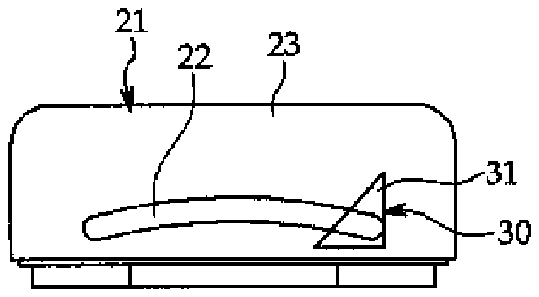
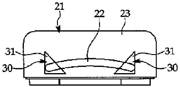
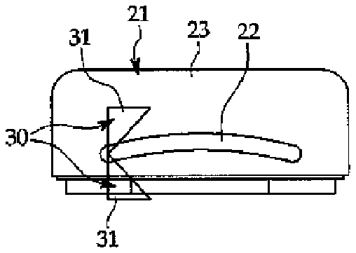
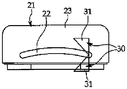
- 10conventional nail clippers
- 11cutter
- 12body
- 13operating lever
- 14pin
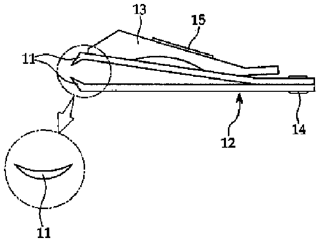
- 15nail file plate
- 20nail clippers
- 21body
- 23heads
- 24upper case
- 25lower case
- 27space portion
- 28nail file plate
- 29fingernail discharging hole
- 30cutter
- 31fixed plate
- 32gap
- 33blade face
- 34cutter blade portion
- 54fingernail
- 56depth adjusting guide
- 57e direction indication protruding guide
- 185between
Abstract
The present invention relates to nail clippers including: a body having a fingernail insertion part formed thereon in such a manner as to insert a fingernail thereinto; and a cutter mounted with respect to the fingernail insertion part on the body in such a manner as to apply a transverse shearing force to the fingernail that has been passed into the fingernail insertion part, the cutter having a fixed plate supportedly fixed to the body and a cutter blade part formed on a partial surface of the fixed plate, the cutter blade part having a blade face adapted to cut the fingernail.
Description
BACKGROUND OF THE INVENTION
[0001] 1. Field of the Invention
[0002] The present invention relates to nail clippers, and more particularly, to nail clippers that cut fingernails by means of a transverse shearing force, thereby safely protecting the fingernails and fingers and performing the fingernail cutting operation with a single action.
[0003] 2. Background of the Related Art
[0004] Conventional nail clippers are structured to insert a fingernail between blades of a cutter in such a manner as to cut the fingernail by means of the pressing force generated by pressing the cutter.
[0005] FIG. 1 is a side view showing a general configuration of conventional nail clippers. As shown, the conventional nail clippers 10 are made by coupling a body 12 made of an elastic steel plate and having a cutter 11 formed at one end thereof by means of press machining with an operating lever 13 adapted to transmit a pressing force by using the principle of the lever.
[0006] The cutter 11 of the conventional nail clippers 10 is generally crescent-shaped, as shown in the dotted circle of FIG. 1 . The cutter 11 is located at the end portion of the body 12 in such a manner as to be opened to insert a fingernail thereinto by means of the elasticity of the body 12 if the body 12 is not pressed by the application of an external force thereto. The upper and lower blades of the cutter 11 have a vertically facing symmetrical structure to correspond with each other, and when the pressing force is applied from the outside to the cutter 11 , they are brought into direct contact with each other to generate a shearing force therefrom.
[0007] The operating lever 13 is shaft-coupled to the body 12 by means of a pin 14 and has a protrusion formed at the end portion thereof so as to press the cutter 11 of the body 12 thereagainst and a nail file plate 15 formed at the inside thereof so as to sharpen or file the fingernail.
[0008] On the other hand, there have been proposed nail clippers that are improved to solve the inconveniences in use and to develop the performances of the general nail clippers 10 , but they just keep the basic structure formed by the cooperative operation relation between the cutter 11 and the body 12 as mentioned above.
[0009] Since the operating lever 12 is pressed to generate the shearing force, further, the conventional nail clippers 10 are hard and inconvenient to use and have the following problems.
[0010] First, as the operating lever 12 should be pressed, it is hard to use the nail clippers 10 , and if misused, the fingernail may cut too deeply, which is not safe in use.
[0011] Since the nail clippers 10 are operated in the state where the portion of the fingernail to be sheared is roughly expected, secondly, it is hard to accurately adjust the length of the fingernail to be sheared.
[0012] As the operating lever 13 should be firmly pressed, thirdly, it is very hard for kids and children to use it.
[0013] Fourthly, the fingernail is cut in such a way as to correspond with the shape of the finger, and therefore, even though the shape of the cutter 11 is formed to correspond with the shape of the finger, the fingernail is not cut to a round shape at a time, thereby performing the cutting operation repeatedly.
[0014] Since the fingernails after the cutting spring toward the outside, lastly, they should be collected again and thrown away.
SUMMARY OF THE INVENTION
[0015] Accordingly, the present invention has been made in view of the above-mentioned problems occurring in the prior art, and it is an object of the present invention to provide nail clippers that are capable of cutting fingernails by means of a transverse shearing force, thereby making it convenient, safe and easy to use.
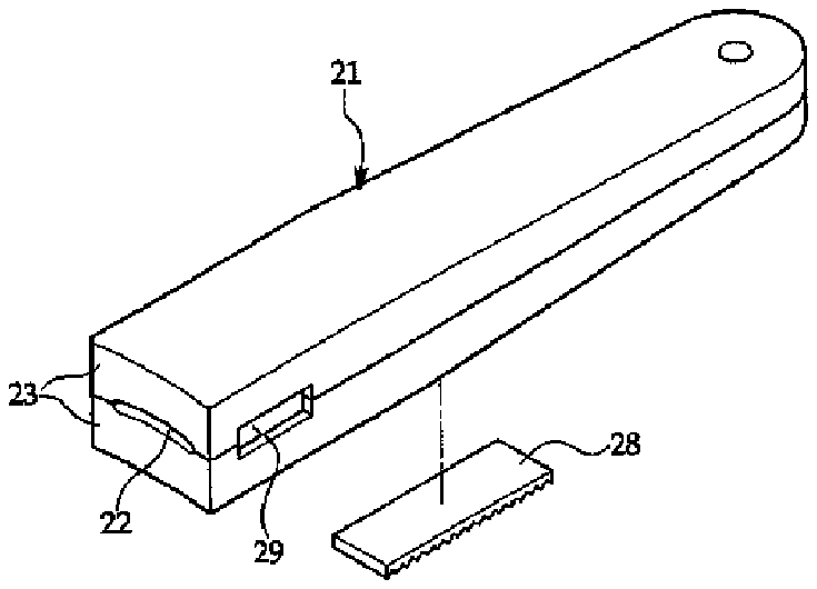
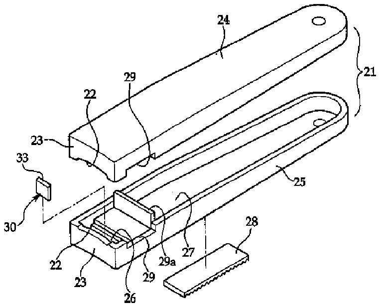
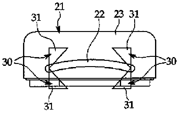
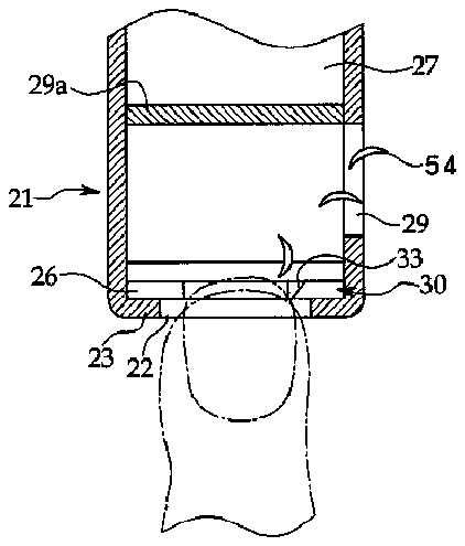
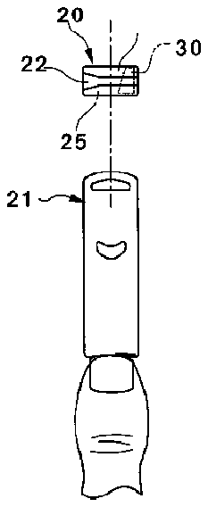
[0016] It is another object of the present invention to provide nail clippers that are capable of being safely used without any damage on fingernails or fingers and at the same time of rapidly cutting the fingernails with a single cutting action.
[0017] It is still another object of the present invention to provide nail clippers that are capable of easily collecting the fingernails after cutting.
[0018] It is yet another object of the present invention to provide nail clippers that are capable of having a function of adjusting a standardized depth of a fingernail to be cut.
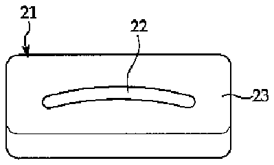
[0019] It is still yet another object of the present invention to provide nail clippers that are capable of allowing a cutting direction when a fingernail is cut to be recognized and permitting an initial position of the fingernail to be cut to be determined, thereby making it easy to use.
[0020] To accomplish the above objects, according to a first aspect of the present invention, there are provided nail clippers including: a body having a fingernail insertion part formed thereon in such a manner as to insert a fingernail thereinto; and a cutter mounted with respect to the fingernail insertion part on the body in such a manner as to apply a transverse shearing force to the fingernail that has been passed into the fingernail insertion part, the cutter having a fixed plate supportedly fixed to the body and a cutter blade part formed on a partial surface of the fixed plate, the cutter blade part having a blade face adapted to cut the fingernail.
[0021] To accomplish the above objects, according to a second aspect of the present invention, there are provided nail clippers including: a body having an upper case and a lower case separately coupled to each other, the upper case and the lower case each having a groove formed at the front side thereof in such a manner as to form a fingernail insertion part when they are coupled to each other, the fingernail insertion part being adapted to insert a fingernail thereinto; a cutter mounted with respect to the fingernail insertion part on the body in such a manner as to apply a transverse shearing force to the fingernail that has been passed into the fingernail insertion part; and a cutter fixing part disposed at the inside of the fingernail insertion part of the upper case and the lower case in such a manner as to supportingly fix the cutter thereto.
[0022] To accomplish the above objects, according to a third aspect of the present invention, there are provided nail clippers including: a body having a fingernail insertion part formed thereon in such a manner as to insert a fingernail thereinto and having a fingernail discharging hole formed near the position where a cutter is located on the side surface of the body in such a manner as to discharge the fingernail cut by the cutter to the outside of the body; and the cutter mounted with respect to the fingernail insertion part on the body in such a manner as to apply a transverse shearing force to the fingernail that has been passed into the fingernail insertion part.
[0023] To accomplish the above objects, according to a fourth aspect of the present invention, there are provided nail clippers including: a body having a fingernail insertion part formed thereon in such a manner as to insert a fingernail thereinto; a cutter mounted with respect to the fingernail insertion part on the body in such a manner as to apply a transverse shearing force to the fingernail that has been passed into the fingernail insertion part; and a fingernail insertion and depth adjusting guide protruded forwardly from a head formed at the front side of the body in such a manner as to have a shape corresponding with the shape of the fingernail insertion part and to induce the contact with the front end of a finger, thereby guiding the insertion of the fingernail into the fingernail insertion part and adjusting the depth of the fingernail inserted into the fingernail insertion part.
[0024] To accomplish the above objects, according to a fifth aspect of the present invention, there are provided nail clippers including: a body having a fingernail insertion part formed thereon in such a manner as to insert a fingernail thereinto; a cutter mounted with respect to the fingernail insertion part on the body in such a manner as to apply a transverse shearing force to the fingernail that has been passed into the fingernail insertion part; and a direction indication protruding guide protruded forwardly from one end of a head formed at the front side of the body in such a manner as to allow the cutting direction of the fingernail and the initial position of the fingernail to be cut to be easily recognized.
BRIEF DESCRIPTION OF THE DRAWINGS
[0025] The above and other objects, features and advantages of the present invention will be apparent from the following detailed description of the preferred embodiments of the invention in conjunction with the accompanying drawings, in which:
[0026] FIG. 1 is a side view showing a general configuration of conventional nail clippers;
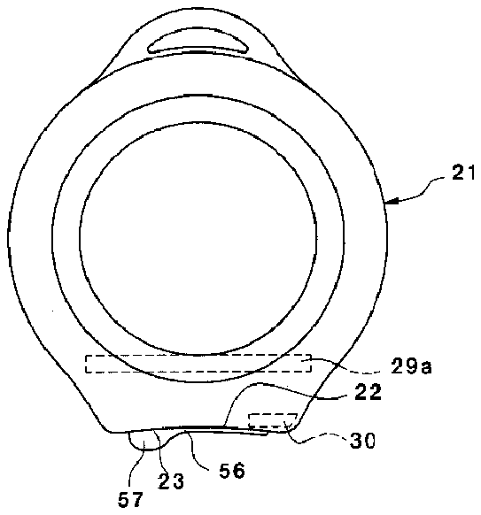
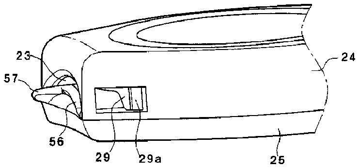
[0027] FIG. 2 is a perspective view showing nail clippers according to a first embodiment of the present invention;
[0028] FIG. 3 is an exploded perspective view showing the nail clippers according to the first embodiment of the present invention;
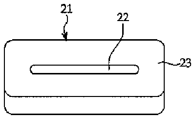
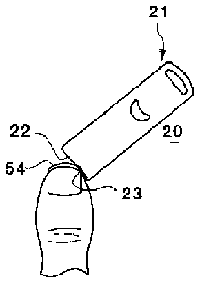
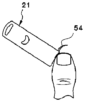
[0029] FIGS. 4 a and 4 b are front views showing a fingernail insertion part of the nail clippers according to the first embodiment of the present invention, wherein FIG. 4 a shows a horizontal fingernail insertion part and FIG. 4 b shows a round fingernail insertion part;
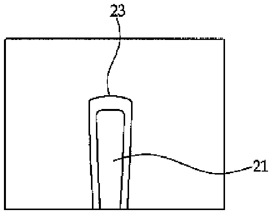
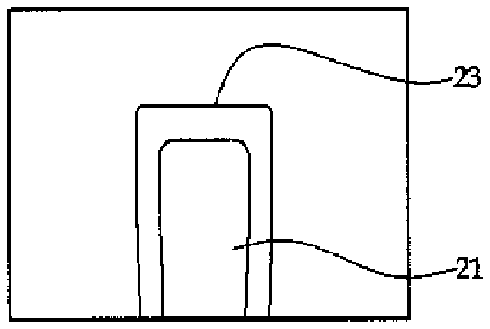
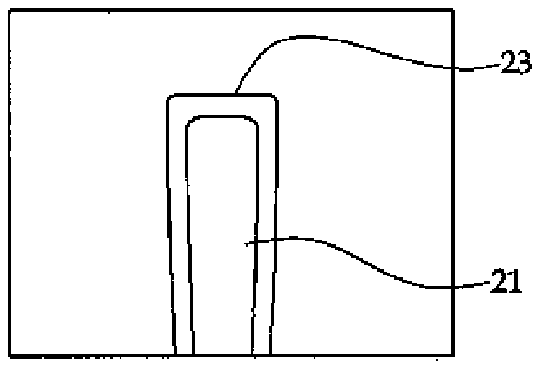
[0030] FIGS. 5 a to 5 c are views showing a head of the nail clippers according to the first embodiment of the present invention, wherein FIG. 5 a shows an outside rounded head, FIG. 5 b shows a horizontal plane head, and FIG. 5 c shows an inside rounded head;
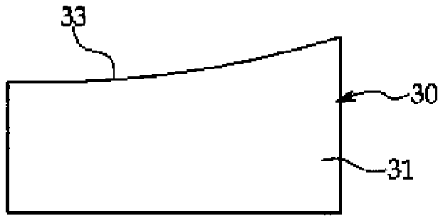
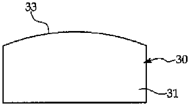
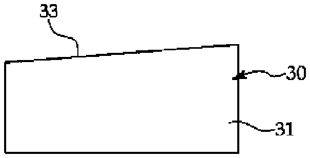
[0031] FIGS. 6 a to 6 c are front views showing examples of a single cutter of the nail clippers according to the first embodiment of the present invention, wherein FIG. 6 a shows a single cutter having a rounded blade face, FIG. 6 b shows a single cutter having a rounded blade face, and FIG. 6 c shows a single cutter having a straight line blade face;
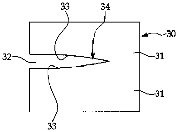
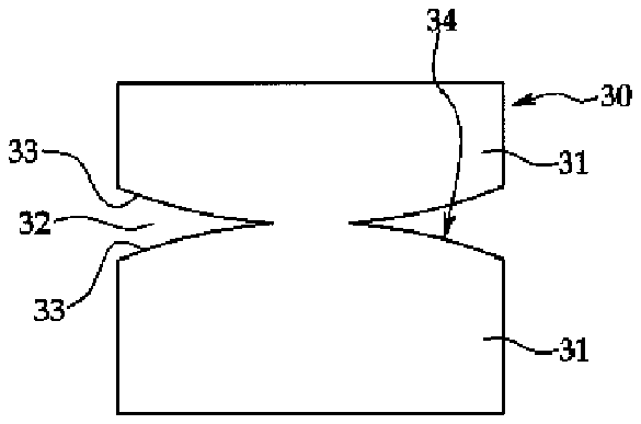
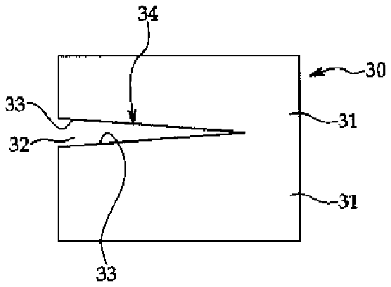
[0032] FIGS. 7 a to 7 c are front views showing other examples of a single cutter of the nail clippers according to the first embodiment of the present invention, wherein FIG. 7 a shows a single cutter having a rounded blade face, FIG. 7 b shows a single cutter having a rounded blade face, and FIG. 7 c shows a single cutter having a straight line blade face;
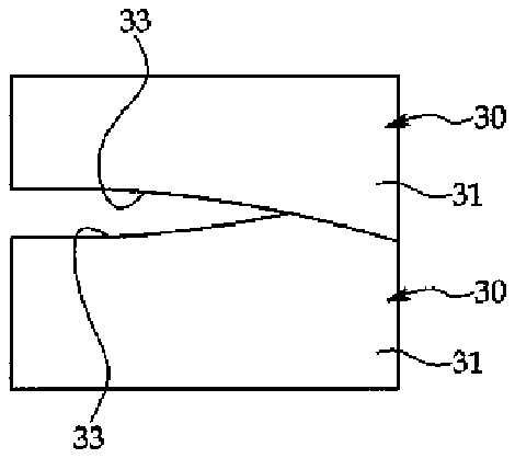
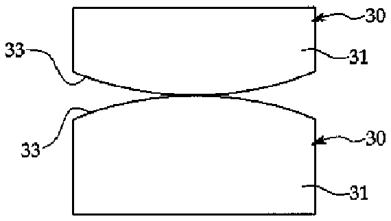
[0033] FIGS. 8 a to 8 c are front views showing examples of a double cutter of the nail clippers according to the first embodiment of the present invention, wherein FIG. 8 a shows a double cutter having rounded blade faces, FIG. 8 b shows a double cutter having rounded blade faces, and FIG. 8 c shows a double cutter having straight line blade faces;
[0034] FIGS. 9 a and 9 b are sectional views showing examples of the mounting of the cutter of the nail clippers according to the first embodiment of the present invention, wherein FIG. 9 a shows a cutter for left direction cutting and FIG. 9 b shows a cutter for right direction cutting;
[0035] FIGS. 10 a to 10 c are sectional views showing other examples of the mounting of the cutter of the nail clippers according to the first embodiment of the present invention, wherein FIG. 10 a shows a cutter mounted at a left side, FIG. 10 b shows a cutter mounted at a right side, and FIG. 10 c shows a cutter mounted at left and right sides, respectively;
[0036] FIGS. 11 a to 11 c are sectional views showing yet other examples of the mounting of the cutter of the nail clippers according to the first embodiment of the present invention, wherein FIG. 11 a shows a cutter mounted up and down at a left side, FIG. 11 b shows a cutter mounted up and down at a right side, and FIG. 11 c shows a cutter mounted up and down at left and right sides, respectively;
[0037] FIG. 12 is a plane sectional view showing a main portion of the use state of the nail clippers according to the first embodiment of the present invention;
[0038] FIG. 13 is a schematic view showing the process of using the nail clippers according to the first embodiment of the present invention;
[0039] FIG. 14 is a plane view showing the whole configurations of nail clippers according to a second embodiment of the present invention;
[0040] FIG. 15 is a perspective view showing one side of the main portions of the nail clippers according to the second embodiment of the present invention; and
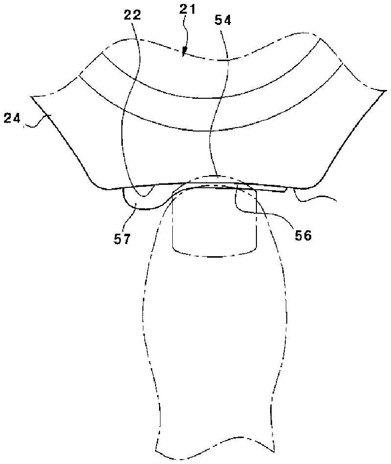
[0041] FIG. 16 is a schematic view showing the process of using the nail clippers according to the second embodiment of the present invention.
DETAILED DESCRIPTION OF THE PREFERRED EMBODIMENT
[0042] Hereinafter, an explanation on nail clippers according to the present invention will be in detail given with reference to the attached drawing.
[0043] As shown in FIGS. 2 and 3 , nail clippers 20 according to the present invention include a body 21 , a fingernail insertion part 22 provided on the body 21 , a cutter 30 mounted with respect to the fingernail insertion part 22 on the body 21 in such a manner as to apply a transverse shearing force to a fingernail that has been passed into the fingernail insertion part 22 , and a hole 29 formed near the position where the cutter 30 is located on the side surface of the body 21 in such a manner as to discharge the fingernail cut by the cutter 30 to the outside of the body 21 .
[0044] The body 21 is an independent body having a movable structure, and otherwise, even though not shown, it may be directly fixed to a given structure.
[0045] The body 21 has an upper case 24 and a lower case 25 that are separately coupled to each other, and also, the body 21 has a partition 29 a disposed at the inside thereof so as to induce the fingernail 54 to the fingernail discharging hole 29 . If the interior of the lower case 25 of the body 21 is formed with a space portion 27 , it is utilized as the space into which the cut fingernails are collected. Further, if a nail file plate 28 is attached to the surface of the lower case 25 , it easily serves to file the fingernail.
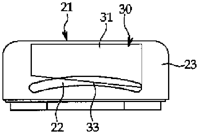
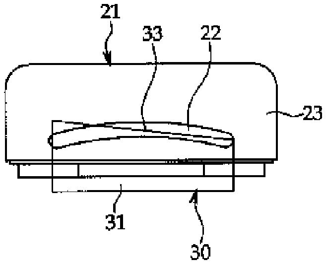
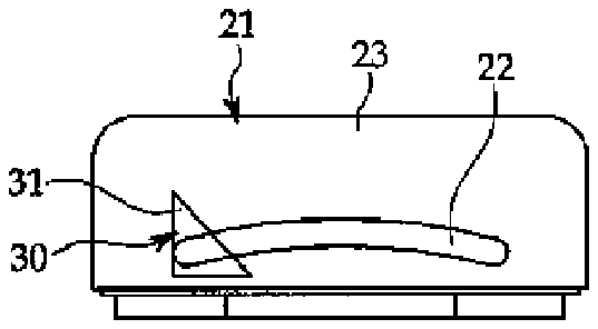
[0046] The upper case 24 and the lower case 25 of the body 21 have heads 23 each having a groove, and when the upper case 24 and the lower case 25 are coupled to each other, the grooves of the heads 23 form the fingernail insertion part 22 .
[0047] At the inside of the fingernail insertion part 22 formed by coupling the upper case 24 and the lower case 25 to each other, is provided a cutter fixing part 26 adapted to supportingly fix the cutter 30 thereto. In the structure of coupling the cutter 30 and the cutter fixing part 26 , if the cutter 30 is detachably mountable, that is, if the cutter 30 and the cutter fixing part 26 are insertedly fixed to each other, the cutter 30 is exchangeable.
[0048] The fingernail insertion part 22 serves to induce the fingernail into the body 21 , and desirably, the fingernail insertion part 22 has a shape capable of easily inserting the end portion of the fingernail thereinto. For example, the fingernail insertion part 22 has a round shape corresponding to the shape of the fingernail (which is shown in FIG. 4 b ). However, the fingernail insertion part 22 may have a horizontal shape into which the fingernail is insertable (which is shown in FIG. 4 a ). In this case, the height of the fingernail insertion part 22 is desirably within about 5 mm a little larger than the thickness of the fingernail.
[0049] The heads 23 of the body 21 on which the fingernail insertion part 22 is formed may have various shapes capable of being naturally brought into contact with the front end portion of the finger, as shown in FIGS. 5 a to 5 c . So as to induce the contact of the finger with the heads 23 , for example, the heads 23 have an outside rounded shape on the front end surfaces thereof (which is shown in FIG. 5 a ), a horizontal plane shape on the front end surfaces thereof (which is shown in FIG. 5 b ), or an inside rounded shape on the front end surfaces thereof (which is shown in FIG. 5 c ).
[0050] On the other hand, the fingernail discharging hole 29 is formed near the position where the cutter 30 is located on the side surface of the body 21 and serves to discharge the fingernail cut by the cutter 30 to the outside of the body 21 . The fingernail discharging hole 29 is formed on one side surface of the body 21 , and otherwise, it is formed on both side surfaces of the body 21 .
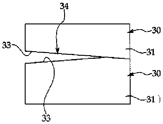
[0051] The cutter 30 is selected from a variety of shapes as shown in FIGS. 6 a to 8 c and is fixedly mounted at the inside of the fingernail insertion part 22 of the body 21 . The cutter 30 has a fixed plate 31 fixed supportedly to a cutter fixing part 26 . The cutter 30 is selected from a single cutter having the single fixed plate 31 and a blade face 33 formed on the single fixed plate 31 , as shown in FIGS. 6 a to 7 c , and a double cutter having the fixed plates 31 disposed opposite to each other and upper and lower side blade faces 33 formed on the fixed plates 31 , as shown in FIGS. 8 a to 8 c . FIGS. 6 a to 6 c show the single cutters 30 , wherein the blade face 33 is formed on one side surface of the fixed plate 31 , and FIGS. 7 a to 7 c show another type of single cutters 30 , wherein a portion of the fixed plate 31 is incised to form a cutter blade portion 34 having blade faces 33 adapted to cut the fingernail inserted into a gap 32 formed by the incision on the fixed plate 31 .
[0052] The blade face 33 has a shape of a straight line or a curved line. In case of the blade face 33 of the straight line, it is desirably formed within a range between 5° to 175° and between 185° to 355°.
[0053] FIGS. 9 a and 9 b are sectional views showing examples of the mounting of the cutter 30 having the single fixed plate 31 .
[0054] As shown in FIGS. 10 a and 10 b , the cutter 30 is mounted at any one side with respect to the fingernail insertion part 22 , and as shown in FIG. 10 c , the cutter 30 is mounted symmetrically or asymmetrically at both sides with respect to the fingernail insertion part 22 . Otherwise, as shown in FIGS. 11 a to 11 c , the two cutters 30 are mounted at the upper and lower sides with respect to the fingernail insertion part 22 .
[0055] On the other hand, as shown in FIGS. 14 to 16 , there are proposed nail clippers according to a second embodiment of the present invention, wherein the nail clippers are provided with a fingernail insertion and depth adjusting guide 56 adapted to induce the contact with the front end of the finger. The fingernail insertion and depth adjusting guide 56 is protruded forwardly from the head 23 of the lower case 25 of the body 21 toward the front side of the fingernail insertion part 22 in such a manner as to have a shape corresponding with the shape of the fingernail insertion part 22 , thereby guiding the insertion of the fingernail into the fingernail insertion part 22 and adjusting the depth of the fingernail inserted into the fingernail insertion part 22 . Desirably, the fingernail insertion and depth adjusting guide 56 is formed as a unitary body with the head 23 of the lower case 25 of the body 21 . Further, the nail clippers according to the second embodiment of the present invention is provided with a direction indication protruding guide 57 adapted to allow the initial position and direction of the fingernail to be cut to be easily recognized. The direction indication protruding guide 57 is protruded forwardly from one end of the fingernail insertion and depth adjusting guide 56 toward the front side of the fingernail insertion part 22 .
[0056] Now, an explanation on an operating method of the nail clippers according to the present invention will be given.
[0057] As shown in FIGS. 12 , 13 and 16 , the finger abuts against the fingernail insertion part 22 of the nail clippers 20 , and the fingernail 54 is inserted into the fingernail insertion part 22 . In this state, if a pushing force is applied to any direction, that is, to a direction A in FIG. 12 and directions A 1 and A 2 in FIG. 13 , the fingernail 54 inserted into the fingernail insertion part 22 is cut by means of the blade face 33 of the cutter 30 mounted at the inside of the fingernail insertion part 22 , and the cut fingernail 54 is discharged through the fingernail discharging hole 29 , without any movement to the interior of the body 21 by means of the formation of the partition 29 a.
[0058] Unlike the conventional nail clippers wherein the fingernail is cut by means of the shearing force generated by pressing the cutter, the nail clippers according to the present invention cuts the fingernail in safe and easy manners at a time just by inserting the fingernail into the fingernail insertion part 22 and moving the finger or the nail clippers in one direction.
[0059] Furthermore, the front end of the finger is brought into contact with the fingernail insertion and depth adjusting guide 56 protruded forwardly from the front side of the head 23 of the lower case 25 , such that the finger does not abut against the cutter 30 , thereby ensuring the safe use of the nail clippers.
[0060] Also, the fingernail is easily inserted into the fingernail insertion part 22 , thereby allowing the kids and children to easily use the nail clippers, and the depth of the fingernail inserted into the fingernail insertion part 22 is checked, thereby adjusting the length of the fingernail to be cut.
[0061] Additionally, when the fingernail is pushed and cut, since the cutting angle is not constantly defined in conventional practices, a user does not know that the fingernail should be cut at any angle, such that the fingernail is cut with the sense of the touch. However, according to the present invention, the end of the fingernail slightly abuts against the direction indication protruding guide 57 and the finger is not separated from the direction indication protruding guide 57 until the fingernail is completely cut, thereby easily cutting the fingernail. Accordingly, the position of a direction where the fingernail is pushed and cut is recognized in advance by the user by means of the formation of the fingernail insertion and depth adjusting guide 56 and the direction indication protruding guide 57 , such that the user can obtain the depth of the insertion of the fingernail and the position of the pushing and cutting direction of the fingernail with the sense of the touch of the front end of the finger with the guides 56 and 57 . Thus, the initial position at which the fingernail is pushed is accurately found, and the fingernail is cut. Also, the depth of the fingernail inserted into the fingernail insertion part 22 is maintained constantly, such that the fingernail is not cut larger or smaller than a desired cutting length.
[0062] As described above, there are provided the nail clippers according to the preferred embodiments of the present invention that are capable of being safely used without any damage on the fingernail and the finger upon cutting and of rapidly completing the fingernail cutting with a single cutting action, thereby providing easy and simple usage to everyone.
[0063] In addition, the nail clippers of the present invention are capable of easily collecting the fingernails cut through the fingernail discharging hole, thereby removing inconveniences of the collection of the fingernails one by one after cutting.
[0064] While the present invention has been described with reference to the particular illustrative embodiments, it is not to be restricted by the embodiments but only by the appended claims. It is to be appreciated that those skilled in the art can change or modify the embodiments without departing from the scope and spirit of the present invention.