

- 5be
- 10closed
- 12july
- 35shoulder
- 50inner surface
- 72recess
Description
July 12, 1938;. Q'GJGRAH ETAL- 2,123,357]
- NIPPERS FQR SKIN AND FINGERNAILS Filed July 3, 1936 Patented July 12, 1938 IUNITED STATES NIPPERS FOR SKIN AND FINGERNAILS Carl Gustav Grah and Paul Giesen, Solingen,
Germany Application July 3, 1936, Serial No. 88,802
3 Claims.
The nippers for skin and finger nails automatically openingby spring action comprise a spring, one end of which is fixed on the inner surface of one arm of the nippers, the other,
5 free end bearing under tension against the other arm of nippers if the nippers are closed. A closing device maintains the nippers in the closed position and, if this closing device is removed, the nippers are automatically opened by the distending spring. The spring is under tension as long as the nippers are closed so that it soon fatigues and becomes slack. Another inconvenience is that the free end of the spring moves along the surface of the opposite handle arm of the nippers, during the closing of the nippers the spring end wears off the material of the surface so that after longer use the closing of the tongue becomes difficult or is prevented.
If no holding device is provided, the spring is rotatable around its fixation pin so that it can be adjusted on the corresponding arm of the nip- J pers to come out of the range, of the opposite handle arm. It is more difficult to store and 7 transport such nippers and the spring has to be 5 adjusted relative to the opposite handle arm to make the nippers ready for use. As the spring is adjustably mounted, it happens frequently that the spring slips off the opposite arm of the handle when the nippers are being used.
All these inconveniences are obviated in the nippers according to the invention in that the free end of the spring is bent and on the inner surface of the opposite arm of the handle a shoulder is provided, the surface of said shoulder 35 along which the spring end slips during the operation being parallel to the bent end of the spring. The rear surface of the shoulder has a recess into which the spring end engages if the nippers are closed.
40 An embodiment of the invention is illustrated by way of example in the accompanying drawing a in which:-
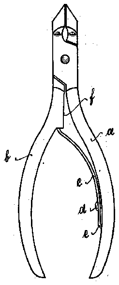
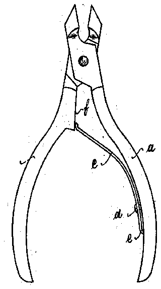
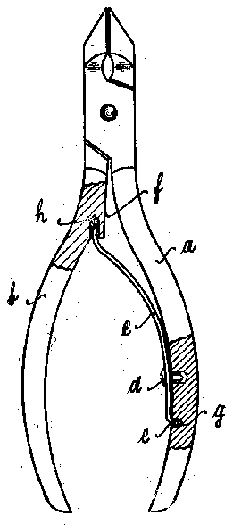
Flg. 1 shows the closed nippers in elevation. Fig. 2 shows the opened nippers in elevation. Fig. 3 shows the closed nippers in elevation partly in section. n
Between the arms a and b oithe handle of the nippers a spring c is arranged, the lower end of which is fixed by a screw, d on the inner surface 50 of the handle arm a. The lower end e of the spring 0 is bent outwards at right angles and engages in a recess a in the inner surface of the handle arm a. The other arm I: of the handle has a projection f on its inner side and the rear Germany' December 23, 1935 face of the projection has a recess 72. designed to receive the free end of spring 0 which is bent towards the pivot point of the arms a, b.
After the nippers have been used, the free end ofspring c is inserted by hand into the recess h of arm b of the open nippers, whereupon the nippers are closed. The spring 0 is under slight tension if the nippers are closed so thatthe bent free end of the spring jams inthe recess h' and securely holds the nippers in the closed 10 position. The tension of the spring 0 is so slight, that; fatiguing of the spring is avoided.
To use the nippers the arms of the handle are spread so that the upper end of the spring 0 is pulled out of recess h and bears against the side face of the projection f, on which the bent of! end of the spring slides to and fro during the operation of the nippers. In the recess h of the projection I cotton wool impregnated with oil or fat is locateddesigned to lubricate the bent free end of the spring 0 so that it smoothly slides on the guide surface of the projection and does not wear into the same.
The invention is not limited to skin and nail nippers but designed for any automatically opening instruments, such as tongs, pincers and scissors, garden-shears and shears for carving birds.
I claim:- 1. Skin and nail nippers opening automatically by spring action and comprising in combination crossing arms pivotally connected at the point of intersection, a plate spring attached to and extending from the lower portion of one of said arms. the second arm of said nippers having an inwardly and downwardly directed projection forming at the face located opposite the first arm a sliding surface for the free end of said spring when the nippers are in their operative position, said projection having a means for removably attaching the free end of said spring thereto, said free end of the spring being slightly curved in the direction to the pivot of the nippers.
2. Nippers as specified in claim '1, in which said means is a recess adapted to receive the free end of the spring when the nippers are in their closed position.
3. Nippersas specified in claim 1, in which said means, is a recess adapted to receive the free end of the spring when the nippers are in their closed position, and that lubricating means for said free end of the spring are provided in said recess.
cam. ous'rav GRAB. PAUL omsan.