


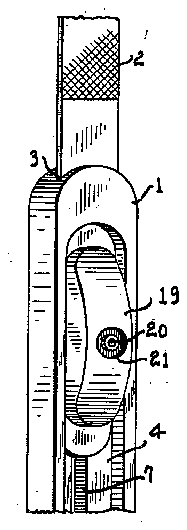
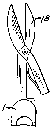
- 1slot
- 2tool blade
- 3opening
- 4groove
- 52 l n vent'or- rd fiicke/vbacher
- 6fastening means
- 7tool
- 8spring member
- 9outer ends
- 10head member
- 12locking slot
- 13 portion
- 14collar
- 19-the'button
- 20the expanded'upset bolt end portion
- 22spring
- 23cylindrical cavity
- 24outer wall portion i
- 26may
Description
May 26, 1942.
IHHI
R. J. RICKENBACHER ADJUSTABLE RETRACTABLE TOOL Filed May 5, 1939 2 Sheets-Sheet l ATTORNEYS May 26, 1942. R. J. RICKENBACHER I ADJUSTABLE RETRACTABLE TOOL Filed May 3, 1959 2 5heets -Sheet 2 Fig. .12
l N VENT'OR- Rd fIICKE/VBACHER 5 Y PM A 7' TORNEYS Patented May 26, 1942 ADJUSTABLE RETRACTABLE TOOL Robert J. Rickenbacher, Columbus, Ohio, assignor to The Kilgore Mfg. Company, Westerville, Ohio, a corporation of Ohio Application May 3, 1939, Serial No. 271,543
7 Claims.
My invention relates to tools, instruments, and the like. More particularly the invention concerns an improvement in devices such as nail files, knives, awls, scissors, saws, keys, and the like hand operated tools wherein the device is retractably sheathed in the handle of the tool.
Anobject of this invention is to provide a tool or instrument of the type aforesaid, wherein the tool is retractable longitudinally of the handle or sheath of the tool in which it is fastened when not in use. This not only protects the tool and working surfaces thereof, but where the tool is carried in the pocket of clothing, fabric, or when packaged or otherwise covered, the sharp surfaces of the tool or instrument are prevented from contacting the adjacent covering and damaging the same.
Another object of this invention is to provide a unitary constructed tool wherein the working tool member is arranged to be positively engaged and forced out of or retracted into the handle or sheath portion thereof.
Another object is to provide an improved device of this character wherein the working blade or tool may be extended to one or more positions and locked against'movement' after so positioning.
Another object is to provide a hand tool of pleasing appearance and in which can be interchangeably mounted difierent kinds of tool blades, as desired.
Still another object-is to provide an instrument comprising a working tool member which can be readily manipulated by the hand to unlock the blade and move it into position for use,
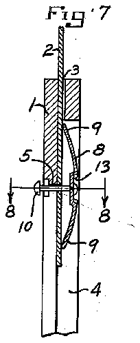
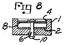
Figure 6 is an enlarged detail sectional view taken on the line 6-6 of Figure Figure 8 is a cross sectional view taken on' the line 8-8 of Figure '7;
Figure 9 is a similarcross sectional view as shown in Figure 8, illustrating a modification wherein the working tool member is detachable from the handle member;
Figure 10 is a pictorial View of a portion of the handle member shown in Figures 1 and 2, wherein a positive locking means is provided for retaining the working tool in retracted position in the handle; 7
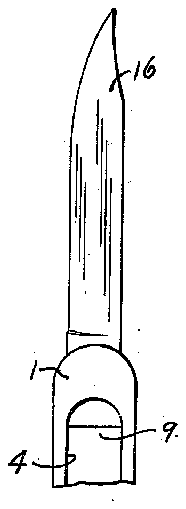
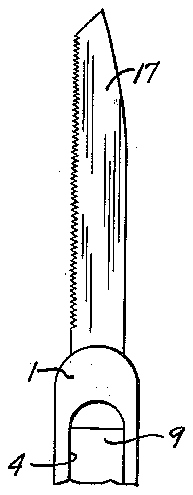
Figures 11, 12 and 13 illustrate the various types of instruments or working tools which are adapted for use with this invention;
Figure 14 is a pictorial view of a fragmentary portion of a tool made according to my invention wherein a spring pressed button member is employed for positioning the tool blade;
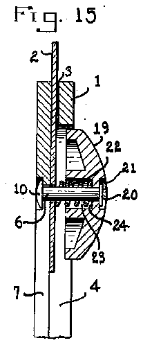
' Figure 15 is a vertical section view of the form shown in Figure 14, illustrating the particular arrangement of the parts of this improved construction.
and whereby the instrument is automatically locked in position upon release of pressure against the tool blade moving member.
A further object is to provide a retractable tool of improved construction wherein a spring pressed button, attached to the tool blade and slidably retained in the sheath-like handle, forms the means for moving and holding the tool blade firmly in any desired position.
In the accompanying drawings:'
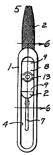
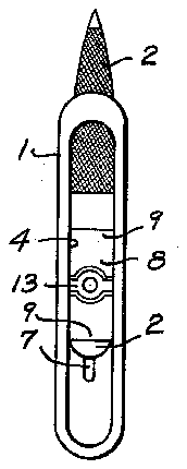
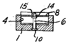
Figure 1 is an enlarged pictorial view of a nail Referring to the drawings in detail, the numeral l designates the tool handle or sheath portion of the device, which may be made of synthetic plastic materials, synthetic resin, shell, bone, glass, ivory, wood, metal, or any other suitable-material. v The working tool member 2 is secured tothe handle I so as to be reciprocable forward and backward through an opening 3 formed in one end of the handle portion l. This opening will be of sufl'lcient size and shape to accommodate the working tool means. The rear portion of the-tool 2; is slidably vmounted in the groove 4 formed longitudinally of the handle I, as shown file embodyingmy'invention', wherein the file riveting. or suitable fastening means 6 passes and which extends through the handle being engaged in the slot 1 formed in the central bottom part of the groove 4. The width'of the slot in the outer ends 9 engage the tool blade 2, as
shown in Figures 6 and 7.
'At the opposite end of the member is prov vided a head member ID. The under side of the head member engages the outer surface H of the handle or sheath l adjacent the longitudinal slot 1. Countersunk portions l2.of a size and shape to 'fitthe head ID are formed at different places along the surface ll adjacent the groove 1. This provides a means of locking the ,working tool member in different positions; Alternatively head locking. means may be. pro.- vided at the extremities of. the slot I and at'the middle, as shown in Figure 10, or only at one end and intermediate the ends, as illustrated in Figures 1 and 2. It will be appreciated that the positioning of the head retaining. depressions I2 may be varied as desired. I
To enhance the manipulation of the tool what I claim as new and desire to secure by Letters Patent is:
1. As an article of manufacture, a unitary working tool and tool-receiving handle therefor, said handle having'a longitudinal grooveon one side in which said tool is adapted to reciprocate, means comprising an elongated slot on the opposite side and of less .width than said groove in communication with the groove, and pin means interlocked with said groove and slot and passing through the end portion of said working, tool retained in the handle, and. means comprising a button fastened to one end of said pin and.
, slidably operable in said groove of the handle for the face of .the spring member 8 is preferablyprovided with a central transverse countersunk;
portion 13 to which the fastening means 6 is suitably attached as by forcefitting or riveting, as shown in Figures 6 and 7;
In Figure 9 the fastening means 6 is removably attached to the member 8 bymeans of the collar 14 and nut l threaded onto the end of the member 6. This construction permits the interchanging of various working tools, such as illustrated in Figures 11, 12 and 13. In these figures the knife blade-l6, saw I I and scissors l8 are adapted to be formedor otherwise mount?" ed on a.suitable extension member'which may be interchangeably attached to the fastening means 6 so as to be retractable into i as illustrated in Figure 3.
It will be observedthatreciprocation of the tool blade is accomplished by applying pressure to the spring member 8 to disengage the head member 10 so that it can be moved along the longitudinal. slot 1 to the desired position where upon releasing the pressure from the spring member 8 the fastening means 6 will be drawn to one side so that the head';member It] will engage in the locking slot 12 so as to lock the tool 7 blade in that position.
In the tool construction illustrated in Figures 14 and 15 the spring member 8 (Figures 6 and 7) is replaced by a button [9 which is suitably fastened to the end of the bolt member 6 by riveting or upsetting the end of the bolt .over as at'ZEI (Figure 15).'
'Ihebutton I9 may be formed of any desired wv material. such as wood; metal, resin or the like. Preferably it is formed of a moldable plastic composition which can be readily shaped to an desired form and hardened.
The member I9 is preferably provided with a countersunk portion 2| for accommodating the expanded'upset bolt end portion 20. A compression spring 22 is disposedaround the bolt between the tool blade 2 and -the'button 19. The spring is extended into a cylindrical cavity 23 the handle there-- adjustably positioning said working tool with respect to said handle.
- 2.. As an article of manufacture, a unitary working tool and a tool-receiving handle therefor, said handle having a groove on one side extending-longitudinally of said handle in which said tool is adapted to slide,v slot means of less width than saidgroove in the opposite side of said handle and'communicating with said groove, pin means positioned transversely of the longitudinal axis [of said handle working in said groove and slot and extending through a portion of said to'ol for 'adjustably positioning the work- 'ing tool with respect. to said handle, said slot having spaced depressions foraccommodating an integral head member on said pin means,
and button means connected to'theopposite end of said pin and yieldably retaining said pin and working tool firmly to said handle adapted to be engaged for reciprocating the workingtool in said handle.
. ton connected to one end ofsaid rod member and shaped to engage in said groove for moving said rod in difi'erent positions, andspring means for maintaining said pin and tool blade firmly to said handle... j
4. As an article of manufacture, a longitudinally movable working tool blade member, a slotted handleassociated .therewithfor forming a sheath for, said tool, pin means reciprocable in said slotandinterlocked with said handle and workingtoolQblade means comprising spaced de-.
pressions cooperating with one end of said pin for locking said pin means in difierent positions,
formed in the central body portion of the button l9 and abuts against the outer wall portion i 24, as illustrated in Figure 15. Spring 22 yieldably maintains the tool blade 2 and slidable bolt 6 firmly to the handle. By varying the tension in the spring member 22 the rigidity of the con-- struction and ease of controlled. T 1 7 It will be understood, of course, that this'invention is not limited to the exact details of conoperation. may be readily 'struction and operation since obvious modifications within the scope of this invention may be made by persons skilledin the art. i Having thus fully" described my invention,
springlmeans connectedto said r'eciprocable pin means and-engaging said working tool blade whereby said pin means can be shifted axially in said groove'to movethe end portion of said pin out of said depression when locked therein whereby said working tool blade is movable to a difi'erent position relative to said handle.
5. As an article of'manufacture, a tool' comprising a working blade and attached handle, said blade being retractable into said handle, a
groovein the handle in which said blade is slidable, pin means interlocked" with said groove and extending transversely of the longitudinal axis of said handle and passing through said blade for holding said blade in different positions relative to said. handle, said blade positioning means com- DlflSlI'lg. a button secured to. said transverse extending means,and yieldable means for firmly.
6. In a tool holder, a case open at one side, a
manicure-tool fitted and slidably' mounted in said case, said manicure-tool having an opening,
said case adapted to hold,said manicure-tool in various positions, said case formed with a guide slot, a plurality of retaining openings, and a guide opening, said guide slot of said case arranged to register with said opening of said manicure-tool to hold said manicure-tool in various positions and to limit the extent of the movement of said manicure-tool relative to said case, said retaining openings of said ease arranged to register with said guide slot of said case and with said opening of said manicuretool to hold said manicure-tool in various positions and to limit the extent of the movement of said manicure-tool relative to said case, said guide opening of said case having its wall adapted to retain and hold said manicure-tool in various positions relative to said case, a fastener movable and adapted to hold the part together, said fastener passing through either of said retaining openings and through said guide slot of said case and through said opening of said manicure-tool, said fastener having its head fitted for engagement with either of said retaining openings of said case, and a resilient retainer engaging with said fastener, said resilient retainer adapted for and capable of retaining all parts seated and under tension in any position permitting quick release and adjustment to hold said manicure-tool either withdrawn withinsaid case or in its adjusted positions for use.
7. Ina tool holder, a case open at one side, a manicure-tool fitted and slidably mounted in said ,case, said manicure-tool having an opening, said case adapted to hold said manicure-tool in various positions, said case formed with a guide slot, a plurality of retaining openings, and a guide opening, said guide slot of said case arranged to register with said opening of said manicure-tool to hold said manicure-tool in various positions and to limit the extent of the movement of said manicure-tool relative to said case, said retaining openings of said ease arranged to register with said guide slot of said case and with said opening of Saidmanicuretool to hold said manicure-tool in various positions and to limit the extent of the movement of said manicure-tool relative to said case, said guide opening of said case having its wall adapted to retain and hold said manicure-tool in various positions relative to said case, a fastener movable and adapted to hold the parts together, said fastener passing through either of said retaining openings and through said guide slot of v said case and through said opening of said manicure-tool, said fastener having its head fitted for engagement with either of said retaining openings of'said case, and a retainer having its shank threaded on said fastener, said retainer adapted for and capable of retaining all parts locked against movement in any position permitting quick release and adjustment to lock and hold said manicure-tool either withdrawn within said case or in its adjusted positions for use.
ROBERT J. RICKENBACHER.