
- 3fairly fall
- 5handles
- 6handle
- 7webe-r
- 8angular upper end
- 9blade
- 13blade
- 20screw
Description
F. F. WEBER CUTTING 0k PUNCHING INSTRUMENT 2 Sheets-Sheet 1 Filed Sept. 30, 1948 F rank F. Weber JNVENTOR.
Ahg. 30, 1949; F. F';. WEBE-R 7 80,797
CUTTING OR PUNLHING INSTRUMENT Filed Sept. 30, 194B 2 Sheets-Sheet 2 Frank F. Weber 2g INVENTOR.
BY W
Patented Aug. 30, 1949 UNITED STATES PATENT OFFICE.
Frank F. Weber, Yorkville, 111'.
Application September 30, 1948, Serial No. 51,988
1' 4 Claims. (Cl. 30-29) V v 1 i This invention relates to a novel instrument primarily designed for use in clipping or cutting ingrown toe nails, although adaptable for use in performing other cutting operations or punching operations.
The primary object of the present invention is to provide an instrument of the above kind whose use does not require reaching down to a point in proximity to the work or thing being cut or punched.
Another object is to provide a simple and durable instrument of the above kind which is easy and safe to use, and which is very efficient in operation.
The exact nature of the present invention will become apparent from the following description when considered in connection with the accompanying drawings, in which:
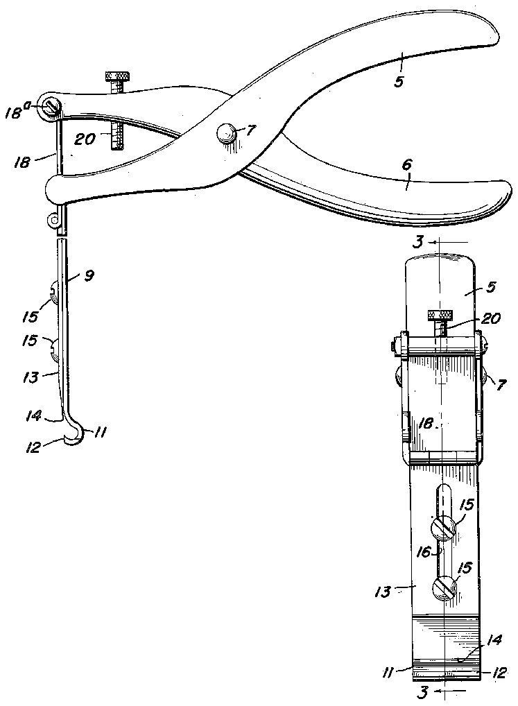
Figure 1 is a side elevational view of a cutting instrument constructed in accordance with the present invention.
Figure 2 is a front elevational view thereof.
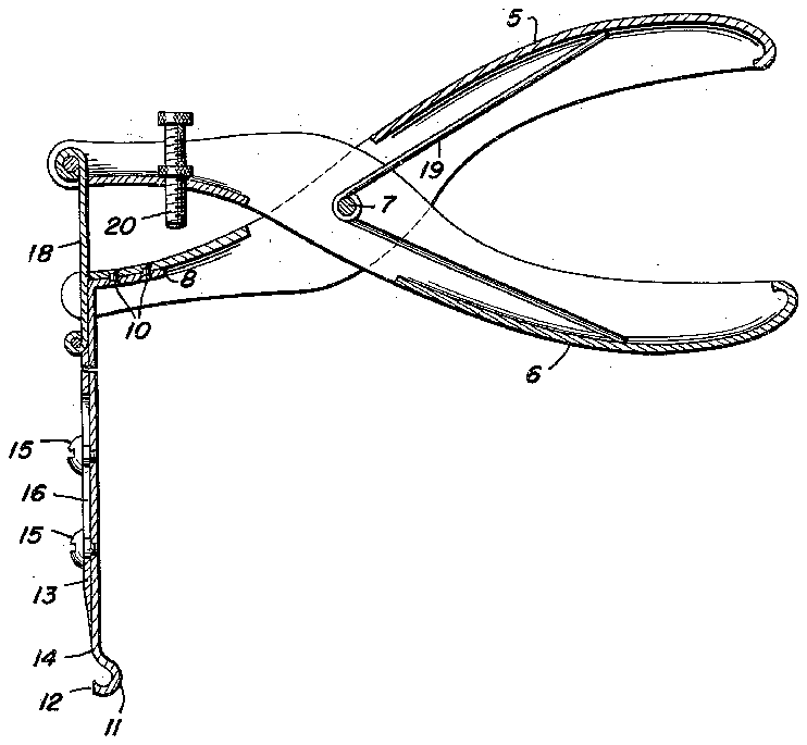
Figure 3 is a vertical section taken on line 3-3 of Figure 2.
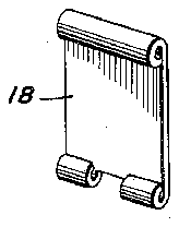
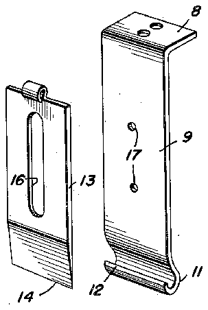
Figure 4 is an exploded perspective view showing the parts of the blade assembly forming part of the instrument shown in Figure 1.
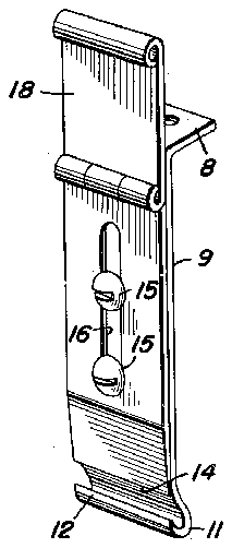
Figure 5 is a perspective view of the blade assembly.
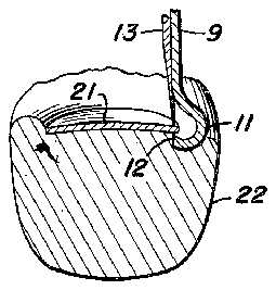
Figure 6 is a fragmentary sectional view showing how the blades are disposed in clipping an ingrown toe nail.
Figure '7 shows a modified form of front cutting blade.
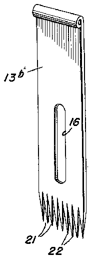
Figure 8 shows a form of front punch plate which may be used in place of the front cuttin blade.
Referring in detail to the drawings, the present instrument includes handles 5 and 6 which are crossed and pivoted to each other intermediate their ends as at I. The forward end of handle 5 is below the forward end of handle 6 and has the angular upper end 8 of a vertical elongated rear blade or plate 9 rigidly attached thereto by rivets I0 or the like. The lower end of blade 9 is formed to provide a rearwardly offset forwardly facing hook-shaped foot portion H whose upturned free transverse edge l2 provides a cutting edge in the same vertical plane as the front face of the flat major upper portion of blade 9. Slidably disposed and held against the front face of blade 9 is a flat vertically movable front blade l3 having a lower cutting edge l4 and detachably connected at its upper end to the forward end of handle 6. As
shown, stud screws l5 freely pass through an elongated slot It provided in blade l3 and are screwed into openings I! of blade 9 to hold said blade l3 in place and guide and upwardly limit it in its vertical movement. A link plate l8 and bolt l8a preferably connects theblade l3 to the forward end of handle '6, and a spring I9 presses the rear ends of handles 5 and 6 apart to normally raise the blade [3. A stop screw is adjustably threaded through the forward end of handle 6 and coacts with the forward end of handle 5 to normally limit downward movement of blade l3, so that the lower cutting edge of the latter will coact with the edge I2 of blade 9 to provide a shearing action but cannot lower to or below the bottom of foot portion H to injure the toe or a support on which said portion II is rested during the cutting operation. The screw 20 may be adjusted, however, to allow the cutting edge I4 of blade l3 to move below foot portion H whenever it is desired to sharpen said cutting edge.
In using the device, the foot portion II is rested on a support and has its edge engaged beneath the work to be cut, whereupon the rear ends of handles 5 and 6 are pressed toward each other so as to force the blade 13 downwardly and perform the cutting operation. When clipping ingrown toe nails, the edge of the foot portion H is engaged beneath the edge of the toe nail 2| and rested upon the adjacent portion of the toe 22 as shown in Figure 6. As the depending blades are relatively long, the user need not reach down to a point in proximity to the work or nail being out.
As shown in Figure '7, the front plate l3a may be adapted for direct connection to the handle 6 so that the link plate l8 may be eliminated, although this will necessitate allowing slight forward and rearward movement of the upper end of said blade as it is moved in using the instrument.
As shown in Figure 8, a gang punch plate I3b may be provided for use in place of the front cutting blade, so that the instrument may be adapted for use in punching holes in leather goods, etc. This punch plate may have its lower end slotted as at 2| to provide spaced pointed punches 22.
From the foregoing description, it is believed that the construction, operation and advantages of the present invention will be readily understood and appreciated by those skilled in the art. Further modifications and changes in details of construction are contemplated such as fairly fall 3 within the spirit and scope of the invention as claimed.
What is claimed as new is:
1. An instrument comprising a pair of handles crossed and pivoted to each other intermediate their ends so that the forward end of one handle is below the forward end of the other handle, a vertical elongated rear blade rigidly attached at its upper end tothat forward handle end which is lower, the lower end :of said rear blade being formed 'to provide a rearwardly offset forwardly facing hook shaped foot portion, said foot portion having an upturned free transverse edge providing a cutting edge in the same vertical plane as the front face of said blade, a spring pressing the rear ends of said handles apart,and' I I a front plate slidably disposed and held against the front face of said rear blade for vertical movement and operatively connected at its upper end to the forward handle end which is upperzmost.
2. .The-nonstructiondefined in=claim 1,.in-combination with means to limit the downward movementof the .frontplate to a point wherein the same coacts'with the edge of the rear blade but above the bottom of .said foot portion. 7
3. An instrument comprising a pair of handies crossed and pivoted to eachother intermediate their ends so that the forward end of one handle is below the forward end of the other handle, a vertical elongated rear blade rigidly attached at its upper end to the forward handle end Which is lower, the lower end of said blade being formed to provide a rearwardly offset forwardly facing hook shaped foot portion, the free transverse edge of said foot portion being upturned and providing a cutting edge in the same vertical plane as the front face iofisaidg blade, a front blade slidably disposed and held against the front face of said rear blade for vertical movement relative thereto, a link plate connecting the upper end of the front blade with the forward handle end which is uppermost, and means to limit downward movement of the front blade to a point wherein its lower end coacts with the edge of the rear blade but above the bottom of said foot portion.
4. The construction defined in claim 3, wherein said means comprises a vertically adjustable stop screw carried by the forward handle end which .is uppermost and coacting with the forward handle end which is lower, to limit downward movement of the front blade.
FRANK F. WEBER.
No references cited.
