- 2section
- 3member
- 4outer ends
- 5outer ends
- 8teat
- 9slot
- 212united states patents number name date
- 340united states patents number name date
- 540hansen
- 782hansen
Description
Feb. 6, 1951 v. HANSEN 2,540,782 NAIL CLIPPER Filed June 3, 1949 T- l g2 E g3 IN V EN TOR. VHA/G HMA/SEN HTTORNEY Patented F eb. 6, 1951 NAIL CLIPPER Vang Hansen, Brooklyn, N. Y., assignor of onethird to Harold A. Large and one-third to Paul Vorwerk, both of Brooklyn,
Application June 3, 1949, Serial No. 96,995
3 Claims.
This invention relates to improvements in nail clippers.
One of the objects oi this invention is to produce a nail clipper that will be readily-operable to trim the finger nails of the user and at the same time will protect the adjacent cuticie from possibility of cutting or injury.
Another object of my invention is to provide a device of the character specied in which the cutting element or knife will be so completely enclosed and protected at all times and especially7 during use that it may be used by children or irresponsible adults.
Another object of my invention is to produce an eicient nail clipper that is small, light and durable, capable of being carried in the pocket of the user and composed of few simple parts that may be easily assembled and is economical to manufacture.
Another object of my invention is in a device of the character specied to provide a iinger-andnail guiding-frame member and a knife member preferably included in a housing composed of a pair of telescoping members, one of which is provided with a depressed curvilinear finger-guiding wall shaped to guide and guard the iingertip and having a narrow nail-insertion arcuate or downwardly-curved slot adapted to receive the projecting portion of a iinger nail only and to ex clude all other parts of the guided nger.
Another object of my invention is to combine with a nail insertion opening of the type specied means within the housing adjacent the said slot for limiting the length of the nail that may be inserted.
With these and other objects in View, the invention comprises the combination of members and arrangement of parts so combined as to con act and cooperate with each other in the peru formance of the functions and the accomplishment of the results herein contemplated, and comprises in one of its adaptations the species or preferred form illustrated in the accompanying drawings, in which:
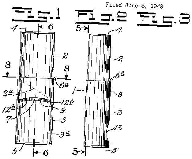
Fig. 1 is an enlarged View in of a nail clipper embodying my the parts in extended or normal position;
Fig. 2 is a similar View in side elevation of the device shown in Fig. l;
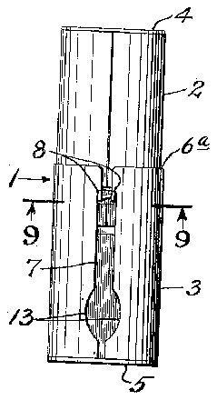
iront elevation invention with Fig. 3 is a similar View in rear elevation of the device shown in Figs. 1 and 2;
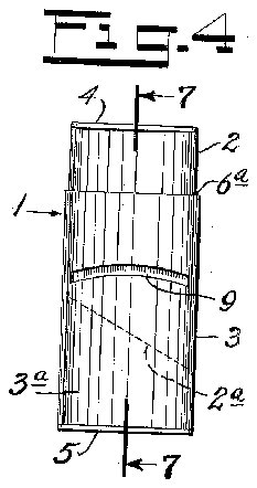
Fig. 4 is a similar1yen1arged view in :front elevation of the device shown in showing the position after tion;
Fig. 5 is a vertical section on the line .5-5 of Fig. 2, looking in the direction of the arrows;
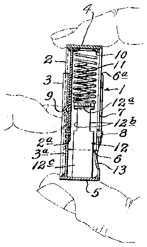
Fig. 6 is a vertical section on the line 6--6 of Fig. l, looking in the direction of the arrows;
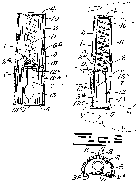
Fig. 7 is a vertical section on the line lof Fig. Il, looking in the direction of the arrows;
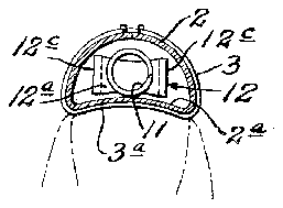
Fig. 8 is a cross-section on the line S-B of Fig. l, looking in the direction of the arrows; and
Fig. 9 is a cross-section on the line 9-9 of Fig. 3, looking in the direction of the arrows.
Referring now to these drawings which illustrate a preferred embodiment of my invention, l indicates an enclosing housing embodying a holding and linger-guiding frame member and a knife bearing to and, as shown, these members comprise a semi-cylindrical inner and outer housing sections 2 and 3 closed at their outer ends 4 and 5 and having open portions and 6a connected together by a telescopic joint. As shown, the sections 2 and 3 are telescopically or slidably engaged and are interconnected by a connection comprising a longitudinal slot l and teat 8. As illustrated, the teat is formed on the inner knife-bearing member 2 and the slot is formed on the outer frame member 3. The telescoping sections so combined provide a device which` not only encloses, conceals and guards all movable parts but is neat in appearance, small in size, (being about one-half the length, width and thickness of the enlarged illustrations shown in the drawings) and light in weight. Consequently the device is capable of being carried in the pocket of the user.
The housing section 3 comprises an outer member having a frame or mounting portion ila and housing section 2 comprises an inner member having a knife edge portion 2a and telescopically movable within the outer member. Both oi these members have depressed frame faces arcuate in cross-sectional conformation to enable the fitting thereinto and the guiding and guarding thereby of the rounded end of the nger of the user. The frame or mounting portion of the outer member thus has a guiding face for the finger tip and this face is provided with a narrow downwardly-curved, arcuate nail-insertion slot 9 passing through the depressed guiding face of the Figs. l to' 3, and parts of the device in contracted having performed a cutting operamember movable relatively therel portions 3 frame or mounting portions of the outer member and extending transversely of said guide face into the guided path of the knife-edge portion 2EL during the telescoping movement of the parts.
In the embodiment shown, y, the inner knifeembodying housing-member 2 preferably has suitablyattached at its upper end by soldered joint I a spiral spring li. This spring Il extends downwardly within the section 2 through the open end thereof and into contact with an abutment member l2 which I preferably insert in the outer member 3 and which provides a supporting shelf l2e that is located just above the nail slot 9 and engages the free end of the spring i i. The abutment member l2 has notched B2b which serve as insertion-limiting surfaces for the nail of the user and said member I2 is U-shaped and open at its lower end to provide legs I2c extending to the bottom of the section 2 of the device.
The rear bottom portion of the outer frame section 2 is also preferably provided with an outlet opening I3 to permit nails which are cut off to be expelled from the Venclosed casing 3.
In the preferred embodiment of my invention shown, each of the members 2 and 3 is formed of a single blank of sheet metal suitably bent in a die to provide the arcuate depressed knife and frame faces while opposite side or wing portions are bent rearwardly toward each other into semi-cylindrical form with the edges in Contact with each other at the rear of the device, while the top and bottom portions are bent transversely to the longitudinal axis of the device so as to close each of the semi-cylindrical members at one end. The opposite ends are open and the open ends of the members are arranged to be telescoped to provide housings or enclosures as hereinabove specified. As illustrated, the inner member ts snugly within the outer member to provide means for guiding the telescopic movement therebetween.
The inner knife-embodying member is preferably formed of a suitable hardened metal such as steel and has at its lower end the knife edge 2a which is preferably disposed on a bias extending transversely from one edge of the face to the other. This bias-arrangement of the knife edge assists in severing of the nails by a cutting or slicing operation rather than by a chopping operation.
In operation, the device is held in one hand of the user as shown in Figs. 6 and '7 while a 'nger nail of the other hand is inserted in the slot in the housing section 2. Upon squeezing of the fingers together the spring Il will be compressed between the upper end of the section 2 and the abutment member as shown in Fig. 7, and the downwardly telescoping'movement of the member 2 within the member 3 will cut oif the inserted portion of the finger nail. This operation is repeated as required to trim the finger nails on one hand of the user whereupon the device is transferred to the other hand and the finger nails on the opposite hand will be similarly inserted in the slot 9 and cut.
It will be obvious that I have provided a very simple, neat, eiiicient and useful nail clipping device having the advantages hereinabove specified.
Having described my invention, I claim:
1. A nail clipper embodying, in combination, an outer tubular frame member having a depressed longitudinally-disposed arcuate fingertip guiding-face portion and provided in said arcuately-depressed face with a transverse nailinsertion slot, a tubular knife-embodying member movable telescopically Within said frame member and having a face of similarly-,depressed arcuate shape provided with a knife-edge portion mounted to move in slidable engagement with the rear surface of said arcuately depressed finger-tip guiding-face portion of the frame member, means engagingboth members for normally pressing said parts resiliently into extended position, each of said members having transverselypositioned finger-holding portions' whereby the squeezing `by the ngers of the user on said iinger-holding portions will enable the knife member t obe depressed and sever a finger nail inserted within said slot.
2. A nail clipper embodying, in combination, an outer tubular frame member having a depressed longitudinally-disposed arcuate ngertip guiding-face portion' and provided in said arcuately-depressed face with a transverse nailinsertion slot, a tubular knife-embodying member movable telescopically within said frame member and having a face of similarly-depressed arcuate shape provided with a knife-edge portion dismsed on a bias extending transversely from one side edge of said depressed arcuate guidingface to the other and mounted to move in slidable engagement with the rear surface of said arcuately depressed finger-tip guiding-face portion of the frame member, means engaging both members for normally pressing said parts resiliently into extended position, each of said members having transversely-positioned finger-holding portions whereby the squeezing by the fingers of the user on said finger-holding portions will` enable the knife member to be depressed and sever a finger nail inserted within said slot.
3. A nail clipper as claimed in claim 2 in which the frame member comprises a lower h ousing section open at its upper end, the knife-embodying member comprises a housing-section open at its lower end and each of said housing sections is composed of a single strip of sheet metal formed and bent intermediate its ends to provide said arcuate depressed portion, side portions extending rearwardly therefrom and transversely extending top and bottom portions,
' VNG HANSEN.
REFERENCES CITED The following references are of record in the file of this patent:
UNITED STATES PATENTS Number Name Date 340,212 Heath et al. Apr. 20, 1886 589,405 Billings Sept. '7, 1897 964,561 Salviolo July 19, 1910 1,908,890 Burns May 16, 1933


