

- 2zengel
- 6march
- 7y y v
- 8line
- 11 fig.v
- 13resilient loop portion
- 14ange
- 16blade
- 18detachable can opener blade
- 31portion
- 32side plates
- 33plate
- 34loop portion
- 35half blade
- 36notches
- 39attachment hole
- 41stop members
- 42space
- 45plates
- 48plates
- 49plates
- 51flange
- 52blade
- 53member
- 54portions
- 55.the slot
- 56flanges
- 59plate members
- 62nail iile portion
- 63plates
- 64side plates
- 65socket devices
- 68blade
- 69pivot means
- 861932 foreign patents number country date
- 95united states patents number name date
- 1321932 foreign patents number country date
- 243the'fback vedges
- 479zengel
- 544zengel
- 606united states patents number name date
Description
March 6, 1951 J. A. zENGEL 2,544,479
FINGER NAIL TRIMMER USING SAFETY RAZOR BLADES IN A NOTCHED BLADE HOLDER Filed oct. 1, 1947 1N V EN TOR.
Patented Mar. 6, 1951 FIN GERNAIL TRIMMER USING SAFETY RAZOR BLADES IN A NOTCHED BLADE HOLDER Joseph A. Zengel, Seattle, Wash.
Application October 1, 1947, Serial No. 777,160
This invention relates to a finger nail trimmer using safety razor blades in a notched bl-ade holder.
An object of this invention is to provide a notched razor blade holder ywhich will receive and hold a safety razor blade in such a manner that the blade can be safely and conveniently used for trimming the iinger nails.
Another object is to provide a device of this nature by which the finger nails can be closely trimmed without danger of cutting the fingers.
'Another object of this invention is to provide a safe and eiiicient nger nail trimmer which uses a razor blade as a cutting means and which is well adapted to have other tools, such as nail files, bottle openers, can openers and the like embodied therein.
Another object of this invention is to provide a nger nail trimmer which utilizes a safety razor blade for trimming purposes and in which the blade can be moved longitudinally in a blade holder means to properly position sharp and not previously used portions of the blade so. that they can be used, the blade, in some instances being positioned so that a portion of said blade extends beyond the end of the holder and can be used like a knife blade.
Other objects of the invention will be apparent from the following description taken in connection with the accompanying drawings.
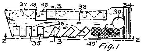
In the drawings Figure 1 is a side elevation of a finger n-ail trimmer constructed in accordance with this invention, showing the same with approximately one half of a broken safety razor blade therein, parts of the blade being shown by dotted lines.
Fig. 2 is a fragmentary edge view looking in the direction of broken line 2- 2 of Fig. 1.
Fig. 3 is a sectional view on line 3-3 of Fig. 1.
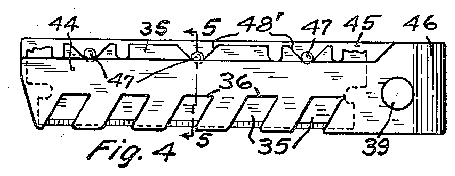
Fig. 4 is a side elevation of a modified form of linger nail trimmer similar to the trimmer shown in Fig. 1.
Fig. 5 is a cross section taken on line 5-5 of Fig. 4.
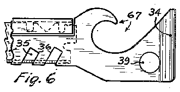
Fig. 6 is a fragmentary View in side elevation of a finger nail trimmer which is similar to that shown in Fig. 1 except that it has a bottle opener formed in the portion thereof that holds the blade.
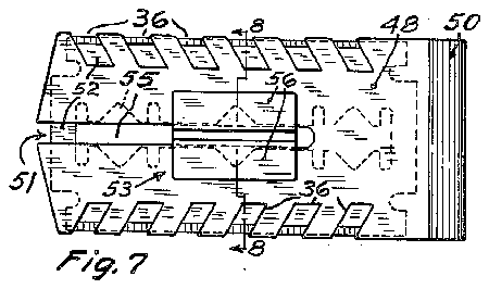
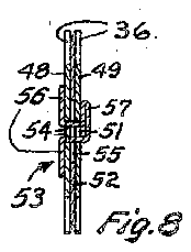
Fig. '7 is a side elevation of a device constructed in accordance with this invention and in which an entire double edge blade, as differentiated from a broken or half blade, is used as the cutting means. Y Y V 7 Claims. (Cl. 30-27) Fig. 8 is a cross section taken on line 8 3 of Fig. 7.
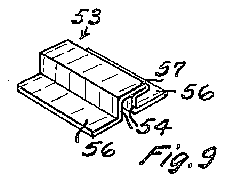
Fig. 9 is -a detached isometric view of a holding clip used in the structure shown in Figs. 7 and 8.
Fig. 10 is a View in elevation of a iinger nail trimmer constructed in accordance with this invention and having a nger nail le made as an integral part thereof.
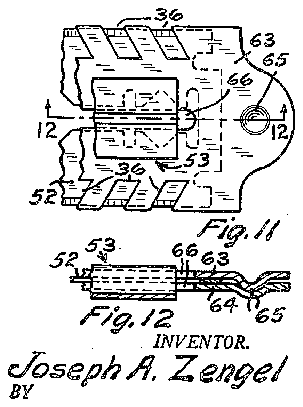
Fig.v 11 is a fragmentary side elevation of a modied form of the type of device shown in Fig. '7.
Fig. 12 is a sectional view taken on line IZ-IZ of Fig. 11. e
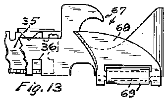
Fig. 13 is a fragmentary elevation of a finger nail trimmer of this type having both -a bottle opener and a can opener combined therewith, a can opener blade being therein shown in an inoperative or closed position.
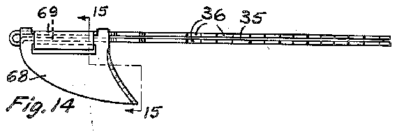
Fig. 14 is an edge view of the device shown in Fig. 13, showing the same turned end for end and showing the can opener blade in an open or operative position. .e
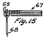
Fig. 15 is -a view partly in section and partly in elevation taken substantially on broken line l5-l 5 of Fig. 14.
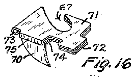
Fig. 16 is a fragmentary perspective View showing a modied form of can opener device in which the can opener blade is a readily detachable part.
All figures of the drawings are shown on an enlarged scale and like reference numerals designate like parts throughout the drawings.
The nger nail trimmer shown in Figs. 1, 2 and 3 comprises two side plates 32 and 33 connected at one, end by an integral resilient loop portion 34 and adapted to receive and hold therebetween one of the halves 35 of a broken safety razor blade of a well knownstandard type. In double edged blades of this type the two halves are connected adjacent their ends onlyand are readily `broken apart to provide the half blade herein shown. The two side by side plates 32 and33 are provided along one edge with-any desired number of registeringv notches 33. The notches 36 can be formed transversely of the plates orv at an angle thereto, as may be desired.- The notches 36 when formed at an angle to Ythe plates better adapt the trimmer for making a slicing or angular cut, as hereinafter explained. Preferably the outer corners of the metal sections between the notches 36 are rounded olf, as shown in the drawings, to obviate the possibility of scratching the outer surfaces of the finger nails in the use of this linger nail trimmer. 1 i 1 The side plates 32 yand 33 are preferably oi different width and the edge portion 31 of the Wider side plate 33 opposite the notches 33 is bent U shape as shown in Figs. l and 3, so that this portion 31 can be selectively used to support the rear edge portions of broken or whole blades of two different widths, as hereinafter explained. Preferably a notch 38 is provided in the plate 33 and the doubled over edge portion 31 and said notch extends into the plate 32. This notch facilitates pushing a blade out of the holder.
Preferably an attachment hole 39 is provided in the side plates 32 and 33 nearthe loop portion 34 so that this device can>an be attached 'to a lkey ring, chain or the like. Also preferably a roughened or serrated surface 45 is provided on the blade holder, such as on the plate 32 to serve as a finger nail le.
To facilitate the use either of one half 35 of a relatively thin double .edged blade, as shown vin Fig. 1, or of a standard-safety razor blade 4l of narrower vwidth but of greater thickness, as shown in Fig. 3, the bent over portion 31 of the plate 33 is positioned relatively closetothe opposed side of said-plate 33 so as to leave therebetween a space 42,?Fig33, ljust wideenough to receive the thinner 4half blade 35, Fig. :1, but .not wideenough tore- 'ceive`the thicker blade 4I, Fig. 3. When .a .half blade 35 is used in this holder, *as shown Ain Fig. 1, the'fback vedges 243 of this half blade '35 `will rest against and be supported .by the part forming the bottom of the space 42. This will properly :position .-the .cutting :edge portion of the half blade 35. When a thicker Vblade 4I of fa narrower :standard 'width .is fused .in this holder ztheoack :edge .portion .of-this narrowerfbnt ythickereblad'e will rest gagainstandtbe stopped and positionedby .the forward edge of the bent over portion 31. In each instance the blade2i-5 or 4i is so positioned by the stop means that the notched 'edgeportion of theplates 32and 33 Aex- .35 about one-sixteenth of an inch Widehave been v found to be satisfactory.
The :plates 32 and 33 are resiliently connected :by the loop portion 34 and 4will engage iwith the sides Aof ,either ofthe blades 35 or 4i with enough rforce .to firmly .and securelyhold `either of ,said
.blades At the :same time said plates willyield relative .to each other sufficiently to permit easy insertion andremoval of either of theblades. The notch 3B facilitates the removal of either blade .35 or v4| and said notch also facilitates endwise u movement of either blade in the holder to there- -by bring new and sharper portions of the blade in registration with the vnotches 35. Also the blade 35 canjbe turnedendfor endin the holder to bring new and sharper sectionsof the blade into registration with the ynotches 3b.
Also the blade *35 can be positionedso that it extends outwardly from the end of the holder shown -atthe leftiin Fig. 1 and this outwardly extending and unguarded portion of the blade can beused'like a knife blade for finger nail trimming 'or lfor other purposes.
Throughout the following description and on all figures of the drawing hereinafter described the numerals 35,'1'36g391and -43--are used tofdesignate respectively blade members, notches, attachment openings and serrated file surfaces similar to those shown in Figs. 1, 2 and 3.
The blade holder shown in Figs. 4 and 5 is similar to the one shown in Figs. l, 2 and 3 and comprises two side plates 44 and 45 connected at one end by an integral resilient loop portion 45. The plates 44 and 45 have .registering notches 36, of a form hereinbefore described, in one edge portion thereof. Preferably the plate 45 is of greater -width than the plate 44 and is slightly wider than the half 35 of the safety razor blade shown therein. The narrower plate 44 leaves the back edge portion of the half blade 35 uncovered and allows access to said back edge portion of the half blade 35 to facilitate properly positioning said half blade in -the holder. Stop members 41 are engaged by V-shaped notches 48 in the rear edge portion of the half blade 35 and said half blade is thereby positioned `rboth longitudinally and transversely. Thefstop members y41 and notches the holderare relatively positioned so that different portions of the cutting edge of the blade canbe brought into registration with the notches 36 'by turning said blade end for end. Thus if a sharp Ihalf blade -35 is inserted and used until the exposed cutting edge portions thereof become dull it can be turned end for `end to bring previously unused sharp sections thereof into registration xwith the notches 36. Also a blade of narrower width than the blade :member T35, such as the vblade member 4I shown .in Fig. 3, canbe used in the holdershownin Figsl and.5 with the back edge of -the blade resting against the stop membersil-l.
'The blade holder Vshown in Fig. 6 is similar to the blade holder shown in Fig. 1 except that the closed or looped-end portionthereof ris made longer and vwider and is .suitably shaped to form a bottle opener [S1-of a type adapted for removing clinched metal caps from bottles.
The nger'nail trimmer shown-inFigs. 7, 8 and 9 Vis adapted to receive and hold a double edged safety razor blade 52 of standard construction that'has not been broken into two halves as has the .blade 35 shown in Fig. 1. The holder of Figs. 7, 8 and 9 comprises two side `plates 4B and 43 connected with-each other atione end by a resilientloop portion t50. lPlates '43 and 49 have registering notches 36 vin both edges thereof which function in the same Avrnanneras the notches 36 in the previously described figures. Also each plate v48 andrll!) is 'provided with'a longitudinally disposed medialslot 5l which extends inwardly from the end of :the plate opposite the loop 5t. The two plates 48 and 49 register with each other andare adaptedto slidably receive a blade holding and positionngmember 53. The member 53 shown in Figs. 7 and 9 is relatively short but obviously this member can be longer if desired .to provide a holding member of greater strength. The member 53 has two spaced apart portions 54 whicheareadapted to extend throughalongitudinal slot in the blade 52 and through the slots 5i4 in the plates 4B and 49. The portions 54 are provided at one end with .two oppositclydirected transverse 'flanges'55 .and at the other end with one transverse` flange 51. Preferably blade holding member V53 is formed of a single piece of sheet metal bent to provide the desiredshape.
A blade 52 is inserted in the holder 48, 49, 5U by first passingthe flange 51 through .the slot 55 in said blade and then .inserting the blade in an endwise direction 4between the plates 48 and 49. The parts 54 of the blade holding member 53 enter the slots 5| and the flanges 56 and 51 engage the outer sides of the plates 48 and 49 as shown in Fig. 8. The blade holding member 53 thus serves to properly position the blade 52 between the plates 48 and 49 and to firmly interconnect the blade and the holder. Obviously the blade 52 can be longitudinally adjusted between the plates 48 and 49 or can be turned end for end to position previously unused cutting edge portions in registration with the notches 36.
The blade holder shown in Fig. comprises two parallel plate members 58 and 59 and connected by a resilient end loop 68. A blade stop 5| is provided on the rear edge portion of the wider plate member 58 and a nail iile portion 62 of conventional shape is integral with and extends outwardly from an end of said plate member 58. Plate members 58 and 59 are adapted to receive and hold a blade member 35 and have registering notches 36 in one edge thereof, all as previously described.
The blade holder shown in Figs. 11 and 12 is similar in many respects to the blade holder shown in Figs. '7, 8 and 9 except that the two side plates 63 and 64 thereof are separable pieces. Said side plates 63 and 64 are provided near one end with hump and socket devices 65 which functions like dowel means to properly position these plates. The plates 63 and 64Y have slots 68 like the previously described slots 5l and are adapted to receive a blade 52 and a blade holding and positioning member 53 of a type previously described. The member 53 properly positions the blade and securely holds the plates 63 and 64 together. The member 53 is shown broken away in Fig. 11 and, if desired, can be substantially as long as the slot in the blade 52. n
The finger nail trimmer shownin Figs. 13, 14 and 15 is similar i'n many respects to the one shown in Fig. 6 and like parts are similarly numbered. In addition, the handle portion of the device shown in Figs. 13, 14 and 15 has a can opener blade 68 connected therewith by pivot means 69. The blade 68 is foldable alongside of the holder, as shown in Fig. 13, when not in use and can be positioned as shown in Figs. 14 and 15 when it is to be used for opening a tin can. The blade holding means shown in Figs. 13, 14 and 15 is similar to that shown in Figs. 1, 2, 3 and 6 and like parts thereof are similarly numbered.
Fig. 16 is a fragmentary perspective view of a blade holding device adapted to receive and hold a detachable can opener blade 18. The holder of Fig. 16 comprises two side plates l! and 'l2 connected by a resilient loop portion 13. The blade 'Hi has a flange 'M extending at right angles therefrom. When the ange 14 of blade 'mis telescopically inserted, by endwise movement of said blade and iiange, between the plates 'il and 12 and back of a stop member 'l5 on the plate 'H and blade 16 will be rmly supported in the operative position shown. When the can opener blade 'iii is not to be used it is withdrawn endwise from the position shown inFig. 16 and is taken care of by inserting said blade i6 between the plates 'il and l2 either forwardly of the flange 'F4 or at the side of said plates opposite to the iiange ld.
In the use of any of the finger nail trimmers hereinbefore described the edge of a blade at the location of one of the notches 38 is applied to the finger nail like a knife blade to trim the nail. The notches are narrow and the adjacent portions of the side plates shield the skin and 6 fiesh on the ends of the fingers and prevent injury thereto by the blade.
The foregoing description and accompanying drawings disclose preferred embodiments of my invention but it will be understood that changes can be made within the scope of the following claims.
I claim:
1. A nger nail trimmer comprising two side plates disposed in side by side parallel relation and adapted to receive therebetween a relatively thin flat safety razor blade; an integral resilient loop portion at one end of said holder connecting said two -side plates and resiliently urging said-two side plates together to thereby clamp and hold the blade; and registering notches of relatively narrow width in edge portions of said side plates, said notches exposing a short length of the cutting edge of the blade.
2. A finger nail trimmer comprising two side plates disposed in side by side parallel relation and adapted to receive therebetween and hold a relatively thin flat safety razor blade; means positioning the blade between said side plates so that edge portions of said side plates slightly overhang a cutting edge of said blade and provide guard means therefor; an integral resilient loop portion at one end of said holder connecting said two side plates and resilently urging said two side plates together with sufficient force to clamp and hold a blade; and registering notches of re1- atively narrow width in the overhanging edge portions of said side plates exposing a short length of the cutting edge of the blade for application to the finger nail.
3. A linger nail trimmer comprising two side plates of different width disposed in side by side parallel relation with two edge portions thereof flush with each other, said side plates being adaptedto receive therebetween a relatively thin at safety razor blade which is provided with a cutting edge and a back edge; stop means carried by one of said side plates adjacent one edge thereof supporting the back edge portion of the blade and positioning the blade so that the flush edges of the side plates slightly overhang and shield the cutting edge of the blade; and registering notches in the overhanging edge portions of said side plates exposing short lengths of the cutting edge portion of said blade for application to a nger nail.
4. A finger nail trimmer comprising two side plates of different width disposed in side by side parallel relation with two edge portions thereof flush with each other and with another edge portion of the wider side plate protruding beyond the adjacent edge portion of the narrower side plate, said plates being adapted to receive therebetween a relatively thin fiat safety razor blade which has a cutting edge and a back edge; a reversely bent member cariied by the protruding edge portion of the wider plate member extending back toward said narrower plate member and adapted to receive the back edge of the blade and position and support the blade; and registering notches in the flush edge portions of said side plates exposing short lengths of the cutting edge portion of the blade for application to a -lnger nai 5. A nger nail trimmer comprising two side plates of diiferent width disposed in side by side parallel relation with two edge portions thereof flush with each other and with another edge portion of the wider side plate protruding beyond the adjacent edge portion of the narrower T side plate, :said side plates being :adapted `to :Ieceive therebetween safety razor blades V,of differ- 'entithickness and width; 1a ireversely bent blade 4positioning and stop member Ycarried by the pro- Atruding edge portion of the wider plate member :and extending :back toward said narrower plate member in spaced relation from but closely adjacent to the wider plate member, whereby the back edge portion of a thin blade of apredetermined width will be received between said reverselybent member and said wider member 'and will rest Yagainst and be positioned by the bottom portion of said .reversely bent member and a thicker blade of less Width Will be stopped and positioned by the edge portion of said reversely A6. The apparatus as claimed in claim 5 in-l Which a notch vis provided in the back edge por- "tion of the wider plate and in the reversely bent member, whereby pressure can be applied to the back edge of ablade to facilitate removal of the blade from between the side plates.
7. A nger nail trimmer comprising two side plates ofdifferent width disposed in side by side parallel relation with two edge portions thereof -iiushwith each other, said side plates being yadapted to receive .therebetween-a relatively thin Y datssafetyrazorlolade which has 1a-cutting edge 'anda back iedge; ;stop.means 'carried lby one 'of REFERENCES CITED vThe following references are of record in the vfile of this patent:
UNITED STATES PATENTS Number Name Date 1,095,606 Traord May 5, 1914 1,326,596 Hyde Dec. 30, 1919 1,890,535 Ern Dec. 13, 1932 FOREIGN PATENTS Number Country Date 132,086 Great Britain Sept. l1, 1919 .29,888 Denmark July 10, 1922