- 1hinge pin
- 2pusher
- 5arm
- 6arms
- 8hinge tabs
- 9hinge tabs
- 10coil spring
- 15with upwardly-projecting shearing blades
- 18adjacent end edge
- 20projections
- 21catch
- 22pusher
- 23nail cleaner
- 25lip
- 26bent around cross bar
- 27catch
- 28tongue
- 29lip
- 30recess
- 650t: united t es pat t number name date
- 869t: united t es pat t number name date
Description
N 1952 H. E. LANGLEY 2,
MANICURE APPARATUS Filed Nov. 14, 1947 37 HARO LAN LE) ATTORN Patented Nov. 4, 1952 MANICURE APPARATUS Harold E. Langley, Bear River, Nova Scotia, Canada Application November 14, 1947, Serial No. 785,894
4 Claims.
This invention relates to improvements in manicure apparatus and the principal object of the invention is to provide a combination apparatus, the co-operating parts of which may be utilized for cutting, filing and cleaning out the finger nails .as well as for a cuticle tool and tweezers.
Another object of my invention. is to provide a manicure apparatus comprising a pair of manipulating arms hingedly secured at one end and normally biased to open position, with co-operating shearing blades along their longitudinal edges for cutting the finger nails by a shearing action as the manipulating arms are closed against the biasing means.
A further object is to provide the manipulating arms with co-operating shearing blades arranged in overlapping relation whereby the shearing edges will fully pass each other in closed position and will maintain overlapping contact relation in their open position. 7
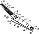
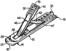
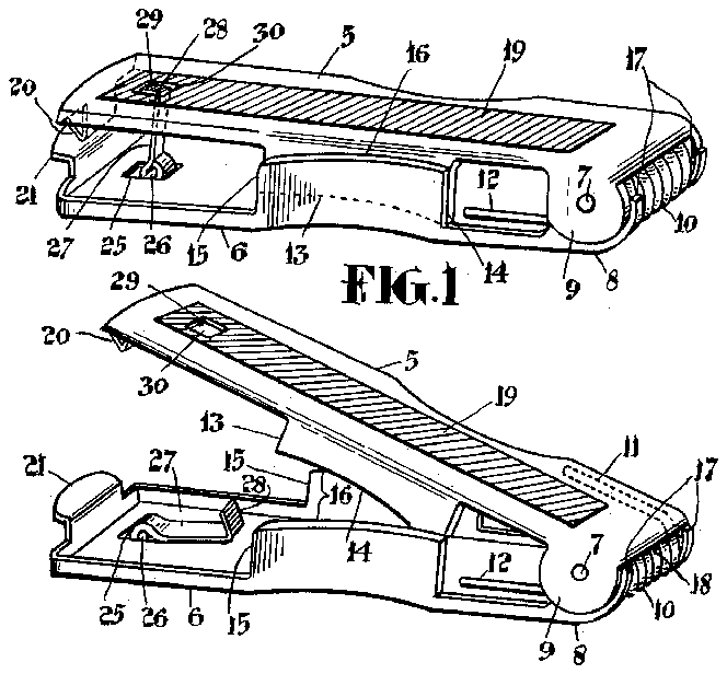
The above and other objects and characteristic features of my invention will be more readily understood from the following detailed descriptiontaken in connection with the accompanying drawings, in which- Fig. 1 is a perspective view of an apparatus embodyin my invention.
Fig. 2 is a view similar to Fig. 1, but showing my apparatus in open position.
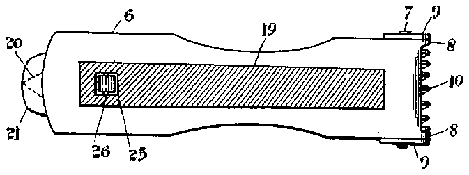
Fig. 3 is a bottom plan view.
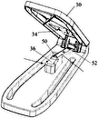
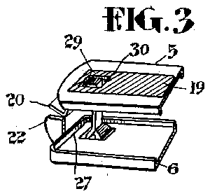
Fig. 4 is a view showing a modified form of my invention.
Referring more particularly to the drawings, 5 and 6 designate upper and lower manipulating arms hingedly secured together at one end by a hinge pin 1. Lower arm 6 is provided with upwardly extending hinge tabs 8 while upper arm 5 is provided with downwardly extending hinge tabs 9 arranged to overlap hinge tabs 8 with tabs 8 snugly fitted between tabs 9 to avoid end play of the hinge or side play of arm 5. A coil spring 10 carried by hinge pin 1 has its end projections II and 12 arranged longitudinally of the upper and lower arms 5 and 6, respectively, to provide biasing means against the closing or bringing together of the upper and lower manipulating arms.
Manipulating arm 5 is provided, along each longitudinal side edge, with a downwardly proiecting shearing blade l3 intermediate its ends, said blade being curved in the longitudinal direction to present inwardly curved outer and outwardly curved inner side wall surfaces and having a bevelled shearing edge [4. .Manipulating arm 6 is similarly. provided with upwardly-projecting shearing blades 15 curved in the longitudinal direction to present inwardly curved outer and outwardly curved inner side wall surfaces, each blade having a bevelled shearing edge It and being arranged outside with the outwardly curved surface of blade l5 in overlapping relation to the inwardly curved surface of blade l3 for shearing action. The blades I3 and I5 are longitudinally tapered to provide receding shearing edges I4 and I6 from their ends nearest hinge connection 1 of arms 5 and 6 to their remote ends. The hinge tabs 8 are provided with stop projections ll adapted to be abutted against the adjacent end edge 18 of arm 5, limiting the opening of the arms 5 and 6, to prevent complete separation of the blades in their open position. In this manner the tapering shearing edges of the blades will be in contact relation at their near ends when the manipulating arms are in their open position so that the finger nail, when inserted for cutting, will be subjected to a shearing action by the blades. The tapering of the blades should not be sufiicient to prevent overlapping of the shearing edges from end to end when the shearing action is completed. It is desirable to keep the co-operating blades in overlapping contact relation at all times to ensure that there will be no danger of collision or crossing of the blades as this would prevent the blades from performing their shearing function as well as damaging the shearing edges. At the same time the blades are held in abutting engagement by the reverse overlapping arrangement of the hinge tabs 8 and 9 and shearing blades [3 and I5. This arrangement tends to maintain the cooperating blades in proper alignment with their adjacent sides in close contact which is necessary in the performance of their shearing function."
The outer surfaces of arms 5 and 6 are serrated, as indicated at l9, to serve as nail files as well as to provide a gripping surface to the arms when manipulating the manicure apparatus in its various functions. One surface should be serrated finer than the other to provide a'fine of arm 6 remote from its hinge connection is pro-f vided with a projection 2| bent upwardly and outwardly but rounded at its end to form a cuticle pushing device. The pointed end, of nail cleaner 20 and rounded end edge of cuticle pusher 2| are formed so as to be flush with one another when their inner surfaces are brought into contact engagement. These inner surfaces are smooth and flat and adapted to be in parallel contact relation to serve as tweezers when the manipulating arms are closed to a parallel position against the biasing of spring I0.
In Fig. 4 I have shown a modified type of cuticle pusher 22 which curves upwardly from arm 6 with its outer vertical edge serving as a cuticle pusher while its upper end edge, coming in contact engagement with nail cleaner 23, functions in cooperation with said cleaner as tweezers. This arrangement has advantages over the pusher 2| in that the narrow gripping surface of pusher 22 is easier to manipulate in the function of tweezers than the broad flat surface of pusher 2|. In this connection it is emphasized that the downward projection of shearing blade I3 should not be sufficient to act as a stop member when the apparatus is in closed position and thereby interfere with the function of the tweezers.
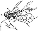
When it is desired to employ my manicure apparatus as a finger nail cutting implement the apparatus may be held between the thumb and forefinger of one hand with the thumb placed lengthwise along manipulating arm 5 and the hinge toward the hollow of the hand. The thumb and forefinger exert pressure on the manipulating arms 5 and 6, respectively beyond the shearing blades. With the lower outside blade it resting against the flesh of the finger below the finger nail to be cut a satisfactory shearing action is obtained. The user is thus able to control the cutting of the nail with greater ease than with the conventional type of manicure scissors. It is equally adaptable for cutting the nails of either hand.
To operate it as tweezers the apparatus is best held between the thumb and forefinger with the thumb on top of arm 5 adjacent the tweezer end.
The cuticle pusher and nail cleaner may be used when the manipulating arms 5 and 6 are in their open position and these devices are easily manipulated for their respective functions.
The manipulating arms, although biased to e o on. a ld, i ose os ion h n. the apparatus is not in use, To this end arm 6 i r e e s n ica t 2 o r n an ning which accommodates a cross bar 26. A metal catch 21 has its thickened end bent around cross bar 26 in pivotal securing engagement therewith The upper end of catch 27 is bent forwardly to provide a tongue 28 engageable with a lip 29 in a recess 30 of the manipulating arm 5. The thickened end of catch 21 which is bent around cross bar 26 should project beyond the outer surface of arm 6. This projecting portion is knurled or milled so that the user may readily manipulate the catch to move the tongue 28 into and out of engagement with lip 29 in recess 30. The lip 25 should be just sufiiciently below the outer surface of arm 5 to allow the tongue 28 to slip easily into place when arms 5 and 6 are parallel and projections 20 and 2| are in contact. With this arrangement it would be impossible for the tongue 28 to protrude through the opening 30 to become accidentally dislodged by catching on pocket or purse linings and, very little I space being left between projections 20 and 2n>| oi 22, there would unlikely be any trouble caused by projection 20 due to its pointed shape.
Having thus described what I now believe to be the preferred embodiment of this invention,
it will be understood that various modifications and alterations may be resorted to without departing from the scope and spirit of the invention as defined by the appended claims.
I claim:
1. A manicure apparatus comprising upper and lower manipulating arms hingedly secured together at one end and normally biased to open position, said upper arm being provided along each longitudinal side edge with a downwardly projecting shearing blade intermediate its ends, said blades having a shearing edge along the lower margin and being curved in the longitudinal direction to present inwardly curved outer and outwardly curved inner side wall sur faces, said lower arm being provided along each longitudinal side edge with an upwardly projecting shearing blade intermediate its ends, said second blades having a shearing edge along the upper margin and being curved in the longitudinal direction to present inwardly curved outer and outwardly curved inner side wall surfaces and being arranged outside of and in overlapping relation to the adjacent downwardly projecting blade of the upper arm, said upper and lower shearing blades being tapered in the longitudinal direction along their outer marginal edges to provide receding shearing edges from their ends nearest the hinge connection of the arms to their remote ends, the degree of taper of said blades being limited to provide positive overlapping of the shearing edges from end to end when said arms are moved about their hinge connection toward each other from the biased open position to a position where the shearing action of the blades is completed.
2. A manicure apparatus as set forth in claim 1 including a stop member carried by one arm at the hinge end thereof and adapted to engage the other arm limiting the opening of said arms to retain at least a portion of the shearing edges of said blades in overlapping contact relation.
3. A manicure apparatus as set forth in claim 1 including side hinge tabs carried by the ends of said arms at the hinge end, said tabs being disposed in reverse overlapping arrangement of the shearing blades to maintain the cooperating blades in alignment with their adjacent sides in abutting engagement.
4. A manicure apparatus as set forth in claim 1, in which the end of the upper arm remote from its hinge connection is provided with an integrally formed projection bent downwardly and outwardly and pointed at its outer end to form a nail cleaner, and in which the end of said lower arm remote from its hinge connection is provided with an integrally formed projection bent upwardly and outwardly and rounded at, its outer end to form a cuticle pushing device, the outer ends of said pointed and rounded projections being flush with each other and the inner surfaces of said projections being flatly engageable to serve as tweezers when the arms are closed to contact position of said projections.
HAR D E. LA E REFERENCES CITED The following references are of record in the file of this patent:
UNITED T ES PAT T Number Name Date 650,869 Redfern June 5, 1900 890,922 Pettibone June 16, 19 08


