- 2plates
- 3plate
- 4plates
- 5cap members
- 6spring
- 7spring
- 8e
- 9notch
- 10rectangular peg
- 11notch
- 13knife blade
- 14blade
- 15pin
- 16partition plate
- 17peg-accommodating notch
- 18spacer block
- 20v-shaped notch
- 21lever
- 22mounting post
- 23second notch
- 26arm
- 27hole
- 29cutting edge
- 34arm
- 35cutting edge
- 36hole
- 37aligned holes
- 38aligned holes
- 3938 for receiving pins
- 4038 for receiving pins
- 41notch
- 42enlarged head
- 43projection
- 44about pin
- 45shoulder
- 46flange
- 47recess
- 60stamping
- 61plate
- 62plate
- 63neck portion
- 65f o
- 66spring arm
- 68tab
- 69tab
- 70tab
- 71line
- 72line
- 73spring
- 74end
- 76flex spring 73 around pin
- 77line
- 78line
- 80notch
- 81portion
- 83plate
- 85fingers
- 86fingers
- 8786 will be bent around shoulders
- 8886 will be bent around shoulders
- 90receive lever
- 91second cover plate
- 92ears
- 93ears
- 94shoulders
- 95shoulders
- 398hunt
- 704hunt
Description
March 22, 1955 w. HUNT 0 POCKET KNIFE AND CLIPPER Filed May 12, 1954 2 Sheets-Sheet 1 a g; zz INVENTOR. :13 Jan/v W Hum 5 0 2... -"Kydi Z QQ; Arm/v5 March 22, 1955 J. w. HUNT 2,704,398
POCKET KNIFE AND CLIPPER Filed May 12, 1954 2 Sheets-Sheet 2 IE 1 E E I 1. ET. 7
62 a f O 65 o IE I. E: E I .1 5-; E 8
II. 3- .LD T
V IN V EN TOR.
JOHN W HUNT United States Patent POCKET KNIFE AND CLIPPER John W. Hunt, Pontiac, Mich.
Application May 12, 1954, Serial No. 429,156
10 Claims. (Cl. 30-142) This invention relates to a combination pocket knife and nail clipper.
It is an object of the invention to provide a pocket knife with a nail clipper without reducing the size of the knife blades. In other words, having in mind that the average man does not want a bulky knife and nail clipper, but does want a knife with at least one fairly good size knife blade and nail clipper, it is desired to utilize normally lost space in the knife casing to accommodate the nail clipper.
Another object is to provide the nail clipper with shielding elements at the side edges of its cutting elements whereby when the device is not being used there will be no danger of the cutting elements snagging the users clothes, as for example when it is deposited in a mans pocket.
Another object is to construct the unit out of a minimum number of parts by forming both side plates of the knife housing out of a single sheet of material.
A further object is to provide the nail clipper with a lever (for bringing the cutting elements together) which needs no latch for holding it in retracted position against the face of the clipper.
Another object is to provide a combination pocket knife and clipper in which the clipper-biasing lever is made as a flat member without a hump portion to project beyond the face of the knife; whereby the device will not be unduly bulky when deposited in a mans pocket.
Other objects of this invention will appear in the following description and appended claims, reference being had to the accompanying drawings forming a part of this specification wherein like reference characters designate corresponding parts in the several views.
In the drawings:
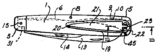
Figure 1 is a plan view of one embodiment constructed according to the invention;
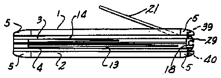
Fig. 2 is a side view of the embodiment shown in Fig. 1;
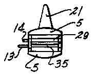
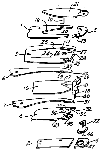
F Fig. 3 is an end view of the embodiment shown in Fig. 4 is an exploded view of the embodiment shown in Fig. 1 with the parts thereof shown in perspective;
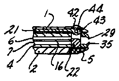
Fig. 5 is a view taken on line 5--5 of Fig. 1;
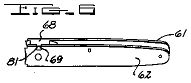
Fig. 6 is a perspective view of a casing and clipperforming unit used in the construction of a second embodiment of the invention;
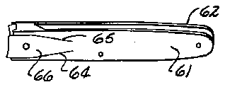
Fig. 7 is a perspective view of the unit shown in Fig. 6 but taken from a different angle of view;
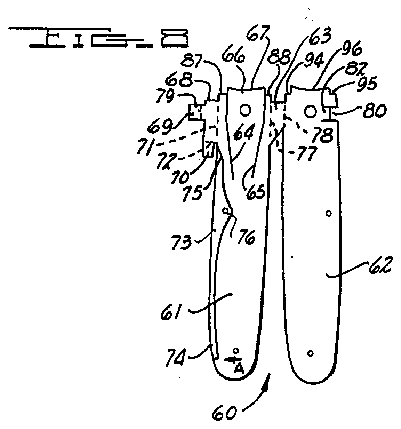
Fig. 8 is a plan view of the unit shown in Fig. 6 taken while it is in the form of a blank prior to its being bent into the form shown in Fig. 6;
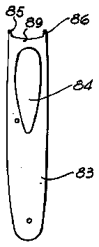
Fig. 9 is a plan view of a plate used to cover one face of the unit shown in Fig. 6;
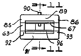
Fig. 10 is an end view of one embodiment of the invention incorporating therein the blank shown in Fig. 8 and the cover plate shown in Fig. 9; and
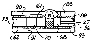
Fig. 11 is a view taken on line 11-11 of Fig. 10.
Before explaining the present invention in detail, it is to be understood that the invention is not limited in its application to the details of construction and arrangement of parts illustrated in the accompanying drawings, since the invention is capable of other embodiments and of being practiced or carried out in various ways. Also, it is to be understood that the phraseology or terminology employed herein is for the purpose of description and not of limitation.
Referring to Figs. 1 through 5, the device there illus- Patented Mar. 22, 1955 trated will be seen to include a pair of cover plates 1 and 2 fixedly secured on the outer faces of liner plates 3 and 4. Secured on plates 3 and 4 at the opposite ends of plates 1 and 2 are cap members 5. Cover plate 1 is cut away at 19 to provide a V-shaped notch 20 for receiving lever 21 in its retracted position against plate 3. A second notch 23 cut in one of cap members 5 receives the apertured ears formed on the upper end of the levers mounting post 22.
Slits at 24 and 25 (Fig. 4) are made in liner plate 3 to provide a spring arm 26, normally lying in the plane of the plate. Hole 27, cut in arm 26, receives mounting post 22 and notch 11, cut in plate 3, receives rectangular peg 10. The free edge of the spring arm is turned down at 28 and provided with a sharp cutting edge 29. Immediately beneath plate 3 but out of alignment with arm 26 is provided knife spring 6, having a notch 9 cut therein to accommodate rectangular peg 10. In the plane of spring 6 there is positioned a knife blade 14 mounted for pivotal movement on pin 15 (Fig. 1). The left end of spring 6 exerts a pressure on blade 14 suflicient to releasably retain it in both use position and retracted position. The right end of spring 6 is undercut at 30 to provide a clearance space for the users finger nail while at the same time preventing the side portion of cutting edge 29 from snagging the users clothes, as when the device is deposited in a mans pocket. A partition plate 16, having peg-accommodating notch 17 cut therein, is provided between spring 6 and a second spring 7. Spring 7 is similar in shape to spring 6 except that its right end is undercut on its upper face (as at 31) instead of on its lower face. Knife blade 13 (Fig. 1) coacts with the left end of spring 7 in the same way that blade 14 coacts with the left end of spring 6.
Plate 4, positioned on the under face of spring 7, is slit at 32 and 33 to form an arm 34. This arm is bent up and provided with a sharp cutting edge 35. Immediately to the left of arm 34 there is provided a hole 36 for accommodating post 22, the flange 46 of which is seated in recess 47 in one of cap members 5. Plates 3 and 4 are provided with aligned holes 37 and 38 for receiving pins 39 and 40, projecting from an>the upper and lower faces of spacer block 18. This block helps hold plates 3 and 4 in spaced relation and at the same time shields the sharp edges 29 and 35 from snagging the users clothes. Notch 41 provides a clearance space for the users finger nail.
Referring to lever 21, shown in retracted position in Fig. 5, there is provided an enlarged head 42 having a projection 43 thereon for releasably retaining the lever in the Fig. 5 position. In the final stage of its movement into the retracted position projection 43 will move up through hole 27 about horizontal pin 44 and snap into position over the upper face of arm 26 (as shown in Fig. 5). Projection 43 eliminates the need for a latch to hold the lever in its retracted position.
In order to move cutting edge 29 from its retracted position into engagement with cutting edge 35, as when it is desired to trim ones finger nail, lever 21 is moved upward about pin 44 until shoulder 45 (Fig. l) is above the upper face of plate 1, after which the lever and post 22 are moved as a unit around the axis of the post for one hundred eighty radial degrees. Lever 21 is then moved down about pin 44 to cause shoulder 45 to engage the upper face of arm 26 and force it down until cutting edge 29 contacts cutting edge 35.
It will be seen that since plate 3 and spring arm 26 are positioned adjacent the relatively short blade 14 the spring arm is free to be moved toward plate 4 without striking a knife blade. It is possible therefore to incorporate the nail clipper into the knife without having to increase the length, Width or thickness thereof.
The modified construction shown in Figs. 6 through 11 includes a stamping 60 having two plates 61 and 62 interconnected by a neck portion 63. Plate 61 is slit at 64 and 65 to provide a spring arm 66 having a sharp cutting edge 67. Projecting from one edge of plate 61 is a large tab 68 having tabs 69 and 70 extending therefrom. Tab 68 is adapted to be bent on line 71 at right angles to the plane of plate 61 and tab 70 is adapted to be bent on line 72 at an angle to tab 68 equal to the inclination of the end 75 of knife spring 73. When the knife blade (not shown) is being moved to closed or open position it exerts a force on the end 74 of spring 73 in the direction of arrow A (Fig. 8) tending to flex spring 73 around pin 76 and remove the slight bow therein. The inclined face portion formed on end portion 75 permits it to ride on inclined tab 70 and compensate for any lengthening of the knife spring which may occur incident to removal of the bow.
Although no knife blades are shown it is contemplated that two knife blades (and hence two knife Springs) will be provided. In order to reduce the thickness of the knife no partition plate is provided between the knife springs. The reader will note that neck portion 63 is wider in the area adjacent plate 61 than in the area adjacent plate 62. The narrow neck portion will allow clearance for a relatively long knife blade while the wide neck portion will strengthen the neck and at the same time allow clearance for a relatively short knife blade.
During assembly of the device plate 61 is bent on line 77 at right angles to neck portion 63, and neck portion 63 is in turn bent on line 78 at right angles to plate 62 so as to position plate 61 parallel to plate 62. Tab 69 is then bent on line 79 at right angles to tab 70 to position portion 81 of tab 69 against the outer face of plate 62 as shown in Fig. 6. The bend portion 79 will then be seated in notch 80 (Fig. 8). In order that portion 81 will not protrude from the outer face of plate 62 its thickness is gradually reduced toward its free edge and the thickness of plate 62 in the area denoted by reference numeral 82 is correspondingly reduced to thereby provide a scarf point between the plate and tab.
Cover plate 83, shown in Fig. 9 and having an oval shaped opening 34 therein (to receive lever 90 in its retracted position) has two fingers 85 and 86 formed thereon. In the assembly operation plate 83 will be positioned in facial engagement with the exposed face of plate 61, after which fingers 85 and 86 will be bent around shoulders 87 and 88 formedan> adjacent spring arm 66. The edge portioan>n of plate 83 between fingers 85 and 86 and denoted by reference numeral 89 is bent around the adjacent portion of arm 66 to form a protective lip therefor.
A second cover plate 91, similar in shape to plate 83 (except that it has no oval-shaped opening) is positioned against the outer face of plate 62 as shown in Fig. 11, and has ears 92 and 93 bent over shoulders 94 and 95 formed adjacent cutting edge 96.
Ears 35. an>86, 92 and 93 overlap the side edges of cutting elements 67 and 96 and prevent them from snagging the users clothes while at the same time the ears are spaced apart a sufiicient distance to permit easy entry of the users finger nail into the space between the cutting ele ments.
The post and lever construction shown in Fig. 11 is the same as that employed in the device shown in Figs. 1 through 5. Hence a detailed description thereof is deemed unnecessary.
Having described my invention, I claim:
1. A combination pocket knife and nail clipper comprising a first plate and a second plate parallel thereto, a relatively long knife blade adjacent said first plate and a relatively short knife blade adjacent said second plate mounted for pivotal movements to and from the space between said plates, said second plate having a plurality of slits cut therein to provide an arm and a shoulder adjacent each side edge thereof, said arm having its free end turned toward said first plate to provide a first cutting jaw, said first plate having an end portion thereof turned toward said arm to provide a second cutting jaw in registry with said first jaw, and spacers between said shoulders and said first plate whereby said first jaw is free to be squeezed against said second jaw but said knife blades a1l"e prevented from binding against said first and second p ates.
2. The combination according to claim 1 wherein one of said spacers includes a block and another of said spacers includes the end portions of a pair of knife springs.
3. The combination according to claim 2 wherein said spacer forming block is notched out to provide a clearance space for the users finger nail.
4. The combination according to claim 2 wherein the end portions of the knife springs are tapered toward the opposed ones of said knife springs to provide a clearance space for the users finger nail.
5. The combination according to claim 1 wherein one of said spacers includes a neck portion formed integrally with said first and second plates and another of said spacers includes an extension integrally formed with one of said plates.
6. The combination according to claim 5 wherein said extension has a tab extending at an angle to the plane of said extension and forming a stop for cammingly engaging the tapering end of a knife spring.
7. A combination pocket knife and nail clipper comprising a first plate and a second plate parallel thereto for receiving a pair of knife blades therebetween, said second plate having a plurality of slits cut therein to provide an arm and a shoulder adjacent each side edge thereof, said arm having its free end turned toward said first plate to provide a first cutting jaw, said first plate having an end portion thereof turned toward said arm to provide a second cutting jaw in registry with said first jaw, and spacers between said shoulders and said first plate, whereby said first jaw is free to be squeezed against said second jaw but said shoulders are prevented from moving toward said first plate.
8. A nail clipper comprising a first plate and a second plate parallel thereto, said second plate having a plurality of slits cut therein to provide an arm and a shoulder adjacent each side edge thereof, said arm having its free end turned toward said first plate to provide a first cutting jaw, said first plate having an end portion thereof turned toward said arm to provide a second cutting jaw in registry with said first jaw, and spacers between sato shoulders and said first plate whereby said first jaw is free to be squeezed against said second jaw but said sllioulders are prevented from moving toward said first p ate.
9. The combination according to claim 8 and further comprising a post rotatably mounted on said first plate and projecting therefrom through a hole in said arm, a lever having an enlarged head pivotally mounted on the free end of said post, said head having a tip portion in the plane of said lever and extending beyond the hole and over the outer face of said arm when said lever is adjacent thereto, the rotatable mounting of said post and the pivotal mounting of said lever permitting said lever to be moved away from said arm with said tip portion moving into the hole, said lever and post to be rotated as a unit for one hundred eighty radial degrees, and said lever to be moved toward said arm, whereby said head will press said arm toward said first plate.
10. A nail clipper comprising a first plate and a second plate, an arm on said second plate having its free end turned toward said first plate to provide a first cutting jaw, said first plate having an end portion thereof turned toward said arm to provide a second cutting jaw in registry with said first jaw, a post rotatably mounted on said first plate and projecting therefrom through a hole in said arm, and a lever having an enlarged head pivotally mounted on the projecting end of said post, said head having a tip portion extending beyond the hole and over the outer face of said arm when said lever is adjacent thereto, the rotatable mounting of said post and the pivotal mounting of said lever permitting said lever to be moved away from said arm with the tip portion moving into the hole, said lever and post to be rotated as a unit about the axis of said post, and said lever to be moved toward said arm, whereby said head will press said arm toward said first plate to effect the desired cutting action on the users finger nail.
No references cited.

