
- 1cutter blade
- 2lower cutter blade
- 4receive headed post
- 5lever
- 6spaced lugs
- 7rivet
- 9nail file
- 22ril
- 45rivet turned
- 180must be swung
Description
A. S. SPEAR NAIL CLIPS Filed Dec. 17, 1957 A ril 22, 1958 United States Patent NAIL CLIPS Arthur S. Spear, Irvington, N. J., assignor to Revlon I mplement Corporation, Irvington, N. J., a corporation of New York Application December 17, 1957, Serial No. 703,410
2 Claims. (Cl. 30-28) The object of the present invention is to provide a nail clip incorporating two cutting blades normally connected for spring action to maintain the cutting areas of the blade apart, the blades being secured together at their rear end by a welding, and being forced into cutting position by a lever. This lever is customarily forked at its front end, and pivoted to a rotating post which is carried by one of the cutter blades and which passes through an opening in the second cutter blade.
In devices of the stated kind, the lever before operation lies in a position close to the top cutter blade, and within the boundaries of the latter. However, being pivoted, it may swing laterally and out of proper position, so that means have been provided heretofore to restrain lateral movement of the top lever, except for when it is manually moved above said restraining means. For example, spaced lugs have been formed at the sides of a pivotally held nail file, to be engaged by the side edges of the lever at its rear end. But unless the nail file, which may be swung from side to side, is first properly positioned on the top cutter blade, the lever will not fit between the nail file lugs, and also the restraint is not adequate, since the file is pivoted to move sidewise.
By means of the present invention the cutter blades are engaged by a rivet of special construction, which will not rotate, which has restraining lugs at its sides, and which will always aiford proper registration with the lever.
The invention will be described with reference to the accompanying drawings, in which:
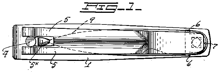
Fig. 1 is an enlarged top plan view of a nail clip embodying the invention, a nail file being shown in dotted lines.
Fig. 2 is a side elevation of the structure shown in Fig. 1.
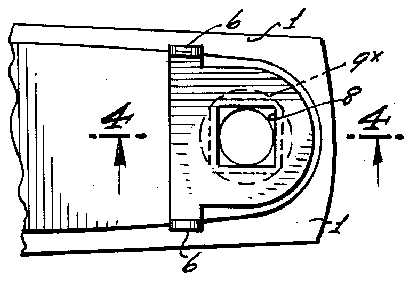
Fig. 3 is a fragmentary top plan view taken at the rear end of the structure.
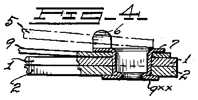
Fig. 4 is a vertical section on the line 4-4, Fig. 3.
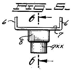
Fig. 5 is a view in elevation of the specially formed rivet.
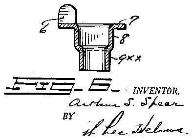
Fig. 6 is a vertical section of the rivet turned 45 degrees from its position in Fig. 5, the section being on the line 6-6, Fig. 5.
Referring to the drawings, I have shown at 1 an upper cutter blade, and at 2 a lower cutter blade, each blade being bent so that the blades diverge toward their cutter ends, and have spring action when the cutter ends are brought together by a lever. The rear ends of the cutter blades are preferably secured together by spot welding,
2,831,247. Patented Apr. 22, 1958 and rearwardly of their front cutting edges the blades are apertured to receive headed post 4 to which lever 5 is pivoted. For such purpose the lever is forked at its front end and provided with opposed pintles (not shown), which enter a slot at 4x of the post. In the position of Figs. 1 and 2 the lever is inactive, and must be swung 180 degrees, and then brought up in an arc and into reverse position for action and so that the contact member 5x thereof will engage the cutter blade 1, whereupon downward movement of the lever will bring the cutting edges together.
In its inactive position the rear side edges of lever 5 are butted by spaced lugs 6 carried by a specially formed rivet 7. Rivet 7 has a plate-like top which directly carries the lugs 7, and it has a squared shank area at 8 which merges into annular area 9xx which may be upset at the base of the lower cutter blade 2, as shown in Fig. 4. The shank area may be flattened at one side only if desired.
Preferably the rivet receives a nail file 9, and to permit the latter to be freely swung outwardly for use the opening therein is of a diameter equivalent to the major distance across the squared shank of the rivet and as shown by the dotted lines 9x, Fig. 3.
It will be seen from the above that the rivet is held against rotation and that when the lever is brought to the position of Figs. 1 and 2 the lever will be held against lateral motion until it is raised for action against the spring pressure of cutter blade 1. It will be understood that the apertures in the cutter blades which receive the squared shank of the rivet will correspond with the latter formation as to one or both of the blades.
Having described my invention, what I claim and desire to secure by Letters Patent, is as follows: i
1. A nail clip comprising an upper and a lower cutter blade, a rivet at the rear end thereof, a post carried by the lower blade and projected through an opening in the upper blade, the post being rotatable, a lever forked at its front end and pivotally connected to the post, whereby the lever may be swung laterally and then reversed in position to bear down upon the top blade for cutting action, said rivet being formed with spaced upwardly projecting lugs adapted to engage the rear side edges of the lever, the rivet entering a squared opening in at least the top cutter blade, and being formed with a shank area adapted to engage said squared opening wall of the top blade, the lower end of the rivet being held by the lower cutter blade, as and for the purpose set forth.
2. A nail clip comprising an upper and a lower cutter blade, a rivet at the rear end thereof, a post carried by the lower blade and projected through an opening in the upper blade, the post being rotatable, a lever forked at its front end and pivotally connected to the post, whereby the lever may be swung laterally and then reversed in position to bear down upon the top blade for cutting action, said rivet being formed with spaced upwardly projecting lugs adapted to engage the rear side edges of the lever, the rivet entering a squared opening in at least one of the cutter blades, and being formed with a shank area adapted ot engage said squared opening wall of the top blade.
No references cited.