

- 10clippers
- 11arms
- 13eyelet
- 14cutting edges
- 16cutting edges
- 17pin
- 18head
- 19notch
- 21hook
- 22lever
- 23bearing surfaces
- 24cross member
- 25openings
- 26opening
- 27cam
- 28guard
Description
Nov. 22, 1960 P. S. WHITTLE GUARD FOR THE CUTTING EDGES OF NAIL CLIPPERS AND THE LIKE Filed Jan. 8. 1960 INVENTOR. Pdu/ 5. Whittle Afiovneys United States Patent GUARD FOR THE CUTTING EDGES 0F NAIL CLIPPERS AND THE LIKE Paul S. Whittle, 624 N. 90th St., Birmingham, Ala. Filed Jan. 8, 1960, Ser. No. 1,352 Claims. (Cl. 30-28) This invention relates to a guard for protecting the cutting edges of nail clippers when the clippers are not m use.
Heretofore, sofar as I am aware, there has not been any type of guard over the cutting edges or blades of nail clippers when the clippers are not being used. The onlyprotection for nail clippers heretofore has been a separate carrying case. When clippers are carried loose in the pocket of a user, the blades sometimes become entangled in the pockets oftentimes causing undue wear and tear on the pockets. Further, coins oftentimes lodge between the cutting edges of the blades or strike the cutting edges, resulting in damage thereto.
By the present invention, the cutting edges in the unoperable position of a nail clipper are protected by a guard Without the use of a separate carrying case, and the guard or protector for the cutting edges is removed from between the cutting edges when the nail clippers are in operable position.
It is an object of the present invention to provide nail clippers having a guard positioned between the cutting edges of the blades and mounted on a movable part of the clipper operating means so that the guard is removed from between the cutting edges when the clippers are ready for use.
It isa further object of the invention to provide a guard for the cutting edges of nail clippers which is secured to the rotary pin extending through the usual pair of outwardly biased spring arms, whereby the guard moves with the pin and is removed from the cutting edges when the nail clippers are ready for use.
Apparatus embodying features of my invention is shown in the accompanying drawing, forming a part of this application, in which:
Fig. 1 is a side elevational view of a pair of nail clippers in inoperable position and showing a guard between the cutting edges;
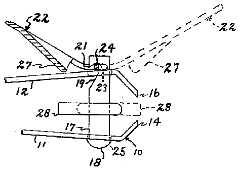
Fig. 2 is a fragmentary .side elevational view, partly in section, of the nail clippers in operable position and showing the guard removed from between the cutting edges;
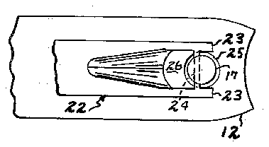
Fig. 3 is a fragmentary top plan view of the nail clippers in Fig. 2 in operable position; and
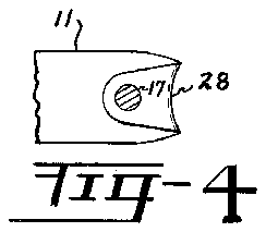
Fig. 4 is a fragmentary view looking generally along line 4-4 of Fig. 1 and showing the guard secured to a pin extending through the arms of the clippers.
Referring now to the drawing, I show a pair of nail clippers of usual construction indicated generally by the numeral and comprising a pair of spring arms 11 and 12 secured to each other at one end thereof by an eyelet 13. The forward ends of arms 11 and 12 are biased outwardly away from each other and have cutting edges or blades 14 and 16 thereon, respectively. A nail file may be pivotally mounted on eyelet 13 for movement to useable position away from arm 12.
A pin 17 extends through arms 11 and 12 adjacent the cutting edges 14 and 16 and is mounted for rotation relative to arms 11 and 12. Head 18 on one end of pin 17 engages arm 11 and a notch 19 on the opposite end of pin 17 forms a hook 21 in which a lever indicated generally by the numeral 22 is mounted. Lever 22 comprises bearing surfaces 23 which bear against arm 12 in the operable position of the nail clippers 10 as shown in Figs. 2 and 3. A cross member 24 extends between bearing surfaces 23 and fits in notch 19. Thus, pin 17 is prevented from slipping from openings 25 in arms 11 and 12 by cross member 24 engaging the inner surfaces defining notch 19. An opening 26 is formed in lever 22 adjacent cross member 24 and is of sufiicient diameter so that lever 22 may pivot in a plane parallel to the longitudinal axis of pin 17 and relative to pin 17 without rotating the pin. Thus, lever 22 may be pivoted over the upper end of pin 17 between the dotted line position shown in Fig. 2 and the position shown in Fig. 1 without rotating pin 17.
A cam 27 is formed on lever 22 and provides a fulcrum therefor. In the operable cutting position of the nail clippers, cam 27 engages arm 12 at a point spaced from the pin 17 and upon pressure being exerted on the end of lever 22 arm 12 is biased downwardly by cam 27 so that the cutting edges 14 and 16 move toward each other to cut nails or the like positioned therebetween.
My improvement comprises a guard or protector 28 secured to pin 17 for rotation therewith. The protector may be made of a plastic material, such as Teflon, a tetrafluoroethylene polymer manufactured by the E. I. du Pont de Nemours and Co., Inc., Wilmington, Delaware. Other suitable materials may be used, if desired. Pin 17 may be secured to guard 28 by a suitable thermoplastic adhesive, or by other means such as having the pin formed of a non-circular cross section and having the guard press fitted thereon. Guard 28 is of a width to cover substantially the entire length of cutting edges 14 and 16 and extends from pin 17 to cutting edges 14 and 16.
In operation, with clippers 10 in inoperable position as shown in Fig. 1, lever 22 is first pivoted to the dotted line position shown in Fig. 2 over the upper end of pin 17. Pin 17 does not rotate during this movement as lever 22 is pivoted in a plane parallel to the longitudinal axis of pin 17 and opening 27 allows lever 22 to move over the upper end of pin 17. Next, lever 22 is moved from the dotted line position shown in Fig. 2 in a plane so that cross member 24 moves perpendicular to the longitudinal axis of pin 17, resulting in the rotation of pin 17 and guard 28. Cross member 24 is engaged by notch 19 and bears against hook 21 so pin 17 and guard 28 rotate therewith to the solid line position shown in Fig. 2 with cam 27 engaging arm 12. Guard 28 is thereby rotated out of the path of the cutting edges 14 and 16 in the position shown in Fig. 2. Upon depression of lever 22, cutting edge 16 moves toward cutting edge 14 for cutting fingernails and the like.
From the foregoing, it will be understood that I have provided a guard for nail clippers which protects the cutting edges and prevents them from becoming entangled in the pockets of a user and thereby removes the necessity of a separate carrying case for the clippers. Further, coins, keys and other paraphernalia which commonly become lodged between cutting edges of nail clippers are prevented from being positioned between cutting edges 14 and 16 thereby protecting cutting edges 14 and 16 from being scarred or nicked.
While I have shown my invention in but one form, it will be obvious to those skilled in the art that it is not so limited but is susceptible of various changes and modifications without departing from the spirit thereof, and I desire, therefore, that only such limitations shall be placed thereupon as are specifically set forth in the appended claims. 7
What I claim is:
l. The combination with a nail clipper embodying a pair of coacting cutting edges together with an operator for holding the edges close together in an inoperative position and for moving them toward each other in operative position, of a guard operatively associated with the operator and disposed when the operator is in inoperative position to lie between the cutting edges, and means effective upon movement of the operator to operative position to move the guard from between the cutting edges.
2. The combination with a nail clipper of the kind having a pair of spring arms secured together at one end and coacting cutting edges on the other end thereof, together with an operator embodying a cam lever movable between operable and inoperable positions and secured to a pin which passes rotatably through the arms near the cutting edges whereby the pin is rotated by said cam lever, of a guard for the cutting edges comprising a piece of material secured to the pin and disposed when the operator is in inoperable position to lie between the cutting edges and when the operator is moved to operable position the guard is rotated with the pin, thereby to occupy a position between the arms and out of the path of the cutting edges.
3. The combination with a nail clipper of the kind having a pair of outwardly biased coacting cutting edges and a pin extending through said arms adjacent said cutting edges to rotate relative to the arms, together with means to rotate said pin, of a guard for the cutting edges comprising a piece of material secured to the pin and disposed to lie between the cutting edges in inoperable position of the nail clipper and to move with the pin out of the path of the cutting edges in operable position of the nail clipper.
4. In a nail clipper, a pair of outwardly biased spring arms secured together at one end and having coacting cutting edges on the other ends thereof, a pin extending through said arms adjacent said cutting edges and being mounted for rotation relative to said arms, a cam lever mounted on an end of said pin and rotating said pin relative to the arms when it is moved in a plane out of parallel to the longitudinal axis of the pin, said cam lever being mounted on said pin for pivotal movement relative to said pin in a plane parallel to the longitudinal axis of the pin, and a guard for the cutting edges comprising a piece of material secured to the pin and disposed when the lever is in inoperable position to lie between the cutting edges and when the lever is moved to operable position to move with the pin to a position out of the .path of said cutting edges.
5. In a nail clipper, a pair of outwardly biased spring arms secured together at one end and having coacting cutting edges on the other ends thereof, a pin extending through said arms adjacent said cutting edges and being mounted for rotation relative to said arms, a lever mounted on an end of said pin and rotating said pin relative to the arms when it is moved in a plane out of parallel to the longitudinal axis of the pin, said lever being mounted on said pin for pivotal movement relative to said pin in a plane parallel to the longitudinal axis of the pin, a cam on said lever adapted to engage the adjacent arm at a position spaced from said pin to form a fulcrum for said lever in operable position of the clipper whereby pressure on said lever when said cam is in engagement with the adjacent arm moves said cutting edges toward each other, and a guard for the cutting edges secured to the pin and being of a size to extend from the pin between the cutting edges and for substantially the entire length of the cutting edges, said guard rotating with said pin and being removed from between the cutting edges when the clipper is in operable position and said cam is in engagement with the adjacent arm.
No references cited.


