- 10upper jaw member
- 11jaw member
- 14rivet
- 15lever
- 16bridge
- 17slot
- 18file member
- 19eyelet
- 20spaced upstanding lugs
- 21feet
- 22bulbous lobe or cam
- 23blade
- 24blade member
- 28offset
- 29adjacent edge
- 30opposite edge
- 31heel
- 32extended hub edge
- 104jaw members
- 132states patents 2,664,624 1/1954 bassett
- 1792,664,624 1/1954 bassett 132'75.5 x
- 477bassett patent
- 624examiner united states patents
- 664examiner united states patents
- 7242,664,624 1/1954 bassett 132'75.5 x
Description
July 19, 1966 J. B. RESWICK 3,261,093
COMBINED NAIL CLIPPER AND KNIFE Filed Oct. 21, 1964 9 20 /6;.
INVENTOR Jim/15s l3. fL-SW/d/K ATTORNEYS United States Patent 3,261,093 COMBINED NAIL CLIPPER AND KNIFE James B. Reswick, 3229 Fairmont Blvd, Cleveland Heights, Ohio Filed Get. 21, 1964, Ser. No. 405,339 6 Claims. (Cl. 30--142) My invention relates to a combined tool providing nail-clipper and cutting-blade functions.
It is an object of the invention to provide an improved device of the character indicated. Specifically, it is an object to provide such. a device with safety features assuring against exposure of sharp edges when folded to inoperative position and positively referencing the cutting blade when extended for use. It is also an. object to meet the foregoing objects with a tool of elemental simplicity and which is effective and foolproof in operation.
Other objects and various further features of novelty and invention will be pointed out or will occur to those skilled in the art from a reading of the following specification in conjunction with the accompanying drawings. In said drawings, which show, for illustrative purposes only, preferred forms of the invention:
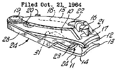
FIG. 1 is a view in perspective showing a preferred tool of the invention, the parts being folded into inoperative position;
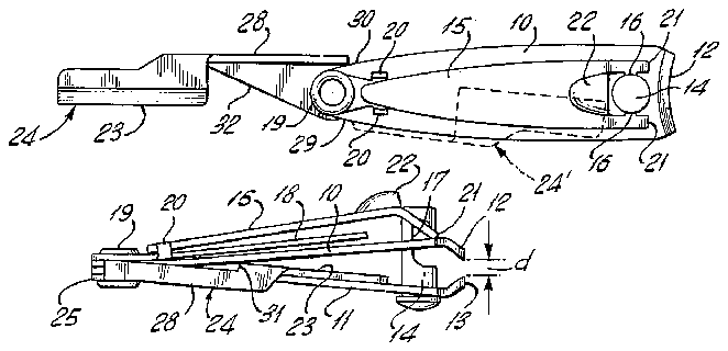
FIG. 2 is plan view of the tool of FIG. 1, with the cutting blade swung to its extended or operative position;
FIG. 3 is a side elevation of the tool of FIG. 1;
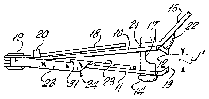
FIG. 4 is a view similar to FIG. 3 but showing the relation of parts when the jaw-actuating lever has been raised from inoperative position;
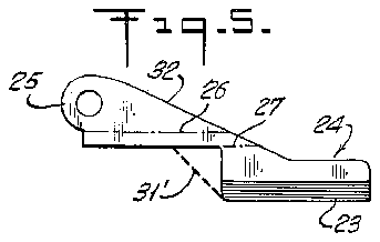
FIG. 5 is a plan view of the blank for the cutting blade element of FIG. 1;
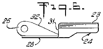
FIG. 6 is a plan view of the element of FIG. 5, after forming to its ultimate shape;
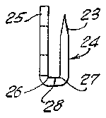
FIG. -7 is a left-end view of the element of FIG. 6;
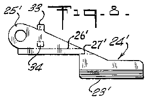
FIG. 8 is a plan view of the blank for a modified form of cutting-blade element; and
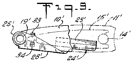
FIG. 9 is a plan view of the formed blank of FIG. 8, shown in assembled relation with parts of a clipper, parts of the latter being broken away and partly in phantom.
Briefly stated, the invention contemplates an improved combined tool featuring a conventional lever-actuated nail clipper with a cutting-blade element pivotally secured thereto, in such manner that the cutting edge of said element is secured in a safe protected position. when the tool is in inoperative condition, and in such manner that the cutting edge is positively referenced to the handle when the cutting-blade 'element is extended for use. The foregoing is achieved without in any way impairing nailclipper functions or effectiveness and without requiring any change in formation of standard nail-clipper parts.
Referring to FIGS. 1 to 7 of the drawings, the invention is shown in application to a standard nail-clipper construction, which happens to be of 'the swingable, reversible-lever type, exemplified in Bassett Patent 2,477,- 782. Thus, the illustrated clipper comprises opposed elongated jaw members 10-11 of stiflly yieldable material such as steel. J aw members 10-11 are connected as by spot-welding at one end, and they diverge to provide normally spaced cutting jaws 12-13 at the other end. A headed pin or rivet 14 passes through aligned openings in the jaw members near the cutting jaws, and an actuating lever 15 is formed with a bridge 16 received in a slot 17 in the rivet 14, to hold the parts in assembled relation.
If desired, and as also shown in said patent, a file member 18 may be pivotally connected by an eyelet 19 to the connected end of the jaw members 10-11, file member 18 being formed with spaced upstanding lugs 20 to receive, locate and retain the free end of the lever 15 when folded as in the position shown in FIGS. 1 to 3. In this folded position, feet 21, which extend just beyond bridge 16, engage jaw member 10 just beyond the longitudinal location at which bridge 16 engages rivet slot 17. J aw members 10-11, when unstressed, are spread apart much more than when assembled; therefore, in the assembled condition, the resilient stress or preload on jaw members 104.1 is reflected via bridge 16 as a strong downward 1fjorce to urge the free end of lever 15 against file mem- As noted above, lever 15 is of the swingable, reversible type, meaning that it must be reversed in order to perform its jaw-actuating function. This is done by raising lever 15 from the FIG. 1 position to the FIG. 4 position, and by then swinging the extended lever about the axis of rivet 14. This operation brings a bulbous lobe or cam 22 into adjacency with the top or outer surface of the upper jaw member 10, so that subsequent lever depression cams the cutting jaws 12-13 together, in conventional fashion.
In accordance with the invention, I provide a cuttingblade function for the described clipper, without requiring any change of clipper parts. The cutting implement is shown as .an elongated knife edge 23 formed at the cutting end of a blade element 24, having at its other end a hub 25, so that it may be pivotally secured by eyelet 19 to the outer surface of one of the jaw members 1011; preferably, 'eyelet 19 is tightly set, so that a good measure of torsional friction characterizes the swinging action of both file 18 and blade member 24, each independently of the other." (In the form of FIGS. 1 to 7, blade member 24 is secured to jaw member 11, and in the form of FIGS. 8 and 9, blade member 24' is secured to jaw member 10.)
As best seen in FIGS. 5 to 7, the blade element 24 is formed from a flat blank, bent along creases 2627 to define an elongated lateral offset 28, which assures that the blade 23 will be received in the space between jaw members 10-11 when in inoperative position. The offset 28 also serves a dual-stop function, limiting swinging movement of blade member 24 when moved to inoperative position, and limiting swinging movement of blade member 24 when moved to the extended or operative position (FIG. 2); at the first of these stop positions, offset 28 abuts the adjacent edge 29 of lower jaw member 11, and at the second of these stop positions, offset 28 abuts the opposite edge 30 of jaw member 11, in which case firm reference is established to the clipper body to enable the same to be an effective handle when cutting with edge 23.
It is an important feature of the invention that means are provided for positive clamping retention of the blade member 24, when in inoperative position. This is accomplished by clamping the jaw members 1011 against opposed faces of blade 23 when handle 15 is set into folded inoperative position (FIG. 3). In this connection, it will be noted that in the inoperative position (FIG. 3) the cutting edges of jaws 1213 are spaced a distance d which is less than the distance d which applies when lever 15 is raised (FIG. -4). I so locate the heel region 31 of blade 23, in relation to the thickness of blade 23 and in relation to the varying spacing of jaw members 10-11 (as lever 15 is operated between the FIG. 3 and FIG. 4 positions) that the heel 31 will freely enter the space between jaw member 1011 when lever 15 is in the FIG. 4 position, but such that on the other hand the FIG. 3 position will establish an interference upon at tempted swinging entry of blade 23 into the space between jaw members 10-11. understood that, if blade 23 is swung into closed position For this relationship, it will bewhile lever 15 is raised (FIG. 4), then subsequent lowering of lever 15 to the FIG. 3 position will involve cammed clamping of jaw members -11 against the heel 31, assuring tight retention of the blade 23 when not in use. On the other hand, by raising lever to the FIG. 4 position, the clamp action is relieved, and finger actuation against the offset 28 or against the extended hub edge 32 will easily bring'the blade 23 into operative position.
As a further feature of the described embodiment, it will be noted that the structural relation of parts inherently permits effective retention of the blade in the event that the lever 15 has been lowered to its inoperative position (FIGS. 1 and 3) before the knife blade 24 is swung into its inoperative position. In this particular event, the heel 31 of the blade will interfere with the inner faces of the jaw members 10,11 as the heel enters the space between these jaw members. Finger pressure applied to flange 28 in the direction of closing the blade 24 to its inoperative position will necessarily locally cam the jaw members 10, 11 slightly apart, thereby assuring positive frictional retention of the folded blade 24. It will be understood that the extent of slight jaw-spreading action achievable in this manner may be enhanced by slanting or tapering the heel 31 orientation in the direction of the hub as indicated by the heavy dashed line 31 in FIG. 5.
In combined tools of the character indicated in which no. file or equivalent member 18 is desired, I prefer the embodmient of FIGS. 8-9 which utilizes essentially the same blade member 24' as described previously at 24. The blade member 24 is shown with primed notation as to reference numerals which correspond with those already described for blade member 24. The blade member 24' is fastened by eyelet 19 to the top surface of the upper jaw member 10 (there being no file member 15 in FIG. 9). and the offset 28' positions blade 23 for reception in the space between jaw members 10-11. In addition, for one location in the region of overlap between lever 15 and hub portion I provide locking means coacting between these overlapping elements. The locking means is shown as spaced lugs 33-34 struck up from and out of the body of hub portion 25, the spacing being such as to receive and locate lever 15 when folded, as shown in FIG. 9. In this situation, it will be appreciated that the clamping action on blade 23' not only holds blade 23' firmly in place when lever 15 is in closed position but also the lugs 33-34 are thus firmly referenced to provide equally firm retention reference for lever 15.
While I have described the invention in detail for the (preferred, forms illustrated, it will be understood that modifications may be made without departing from the scope of the invention as defined in the claims which follow.
I claim:
1. A combined tool, comprising opposed upper and lower elongated jaw members of stifily yieldable material connected at one end and having normallyspaced cutting jaws at the other end, a pivotally mounted operating lever for forcing the jaws together for a clipping operation and arranged to lie adjacent the top surface of the upper member when in inoperative position, said jaws being closer together when said lever is in inoperative position than when said lever is elevated into cutting position, and an elongated blade member-having a hub end pivotally connected to the connected end of said jaw members on the outer surface of one of said jaw members, said blade member having a blade end associated with said hub end via a lateral offset portion, whereby in inoperative position said blade portion may be swung into and received in the space between said jaw members and whereby in operative position said blade member may extend in the direction away from said cutting jaws, the thickness of said blade member being such in relation to the spacing of unconnected portions of said jaw members that when said lever is in elevated position a clearance exists for swinging movement of said blade member between said jaw members and that when said lever is lowered to said inoperative position said jaw members compressionally engage a part of the blade end of said blade member to retain the same should it then be between said jaw members.
2. A tool according to claim 1, in which said blade end includes an elongated cutting edge facing in the direction away from said lateral offset portion, said oifset portion being so located with respect to the blade pivot axis and to said cutting edge and to the adjacent edge of said one jaw member that in the inoperative position of said blade member said offset portion abuts said adjacent jaw-member edge to define a stop which assures against pivoting said blade member between said jaw members to such an extent that said cutting edge protrudes beyond the jawmember edge opposite said adjacent edge.
3. A tool according to claim 2, in which said offset portion extends to a longitudinal position in proximity to the longitudinal location of the blade-pivot axis, Whereby when said blade member is swung to its extended operative position said offset portion may interfere with the opposite jaw-member edge to define a stop so that said jaw members may constitute a firm handle during use of said cutting edge.
4. A tool according to claim 1, in which said blade-hub end is pivotally secured against the outer surface of the lower jaw member.
5. A tool according to claim 1, in which said blade-hub end is pivotally secured against the top surface of the upper jaw.
6. A tool according to claim 5, in which said blade member and said lever have overplapping regions when in their respective inoperative positions, and in which said blade member and said lever haveinterengaging locking elements at the overlapping regions, whereby jawclamped retention of said blade member additionally provides positive retention against accidental swinging dislodgement of said lever when in inoperative position.
References Cited by the Examiner UNITED STATES PATENTS 2,664,624 1/1954 Bassett 132'75.5 X 2,724,179 11/195an>5 Baer 30-143' 3,089,239 5/1963 Loda 30l42 WILLIAM FELDMAN, Primary Examiner.
R. V. PARKER, JR., Assistant Examiner.


