- 11970 4 sheets-sheet
- 4clippers
- 10actuating members
- 12actuating members
- 14base portions
- 16base portions
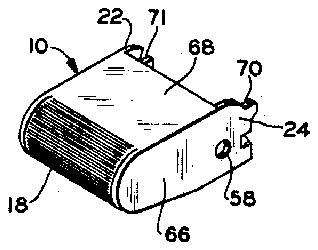
- 18serrations
- 20serrations
- 22bifurcations
- 24bifurcations
- 25read means line
- 26bifurcations
- 28bifurcations
- 30gear teeth
- 32gear teeth
- 34gear teeth
- 36gear teeth
- 37references cited united states patents
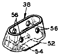
- 38spring member
- 40legs
- 42legs
- 44legs
- 46legs
- 52cutting surfaces
- 54cutting surfaces
- 56apertures
- 58apertures
- 60pins
- 62pins
- 64cam surfaces
- 66side walls
- 68top wall
- 71depression
- 72actuating members
- 74actuating members
- 76side sections
- 78side sections
- 80side sections
- 82side sections
- 84feet
- 86feet
- 92tooth-like projections
- 94tooth-like projections
- 96eyes
- 98apertures or eyes
- 99a cross sectional view taken along lines
- 100serrations
- 102serrations
- 104spring member
- 106legs
- 108spring legs
- 110base sections
- 112base sections
- 114cutting surfaces
- 116cutting surfaces
- 118cam ring
- 120towers
- 122towers
- 124depressions
- 126depressions
- 128apertures
- 130apertures
- 132pin means
- 134pin means
- 136actuating members
- 140serrations
- 142serrations
- 144bifurcations
- 146bifurcations
- 148bifurcations
- 150bifurcations
- 154projections
- 156spring member
- 158legs
- 160legs
- 162shoulder
- 164vise-like teeth
- 166teeth
- 170cam ring
- 172cutting surface
- 174cutting surface
- 178cutting surfaces
- 182eyes
- 184apertures
- 188:yes
- 190apertures
- 194cam surfaces
- 196actuating members
- 198actuating members
- 200tooth-like projection
- 202depression
- 204spring ring
- 206cutting surfaces
- 208cutting surfaces
- 210four apertures
- 212u-shaped rod
- 214leg
- 216other leg
- 218lrilled recess
- 220eye
- 222eye
- 226drilled recess
- 230eye
- 234serrations
- 236serrations
- 238cam surfaces
- 806references cited united states patents
- 933,037 11/1905 wilcox 3028 foreign patents
Description
T. s. BOWERS 'CLIPPERS March 3, 1970 4 Sheets-Sheet 1 Filed March 14, 1968 FIG. 3
FIG. 5
INVENTOR.
S. BOWERS ATTORNEY March 3, 1970 "r. s). abwERs 3,497,956
' cmrrsns Filed llarch 14, 1968 4 Sheets-Sheet 2 INVENTOR. THOMAS S. BOWERS "f Maw ATTORNEY March 3, 1970 'r. s. BOWERS cLIPPERs 4 Sheets-Sheet 5 Filed March 14, 1968 INVENTOR. THOMAS BOWERS ATTORNEY 'r. s; BOWERS March 3, 1970 CLIPPERS 4 Sheets-Sheet 4 Filed March 14, 1968 FIG. I4
FIG. l6 FIG. I8
INVENTOR.
S. BOWERS BY W15 5 A M o H T ATTORNEY United States Patent f 3,497,956 CLIPPERS Thomas S. Bowers, Toledo, Ohio (3366 Mt. Diablo Blvd., Lafayette, Calif. 94349) Filed Mar. 14, 1968, Ser. No. 713,040
Int. Cl. A4511 29/02 US. CI. 30-28 16 Claims ABSTRACT OF THE DISCLOSURE This disclosure pertains to clippers having a pair of acituating members. In one of the embodiments the actuating members are geared together and each is secured to a spring for pivotal rotation with respect thereto by a pin. The spring is housed within the two actuating members and is wider at its base than at its top so that when its base portion is squeezed, cutting surfaces provided on the base are moved toward each other to perform a cutting operation. Cam surfaces are provided on the inner portions of both actuating members so that upon upward pivotal rotation of the actuating members the cams will engage the spring at four places and, due to the geared connection between the actuating members, provide an equal force distribution on the spring to move the cutting surfaces together to perform the cutting operation.
In another embodiment of the invention a cam ring is placed over the cutting spring and each of the actuating members are geared to the cam ring to press it downwardly over the spring upon upward pivotal movement of the actuating members so that the cutting surfaces on the base of the spring are moved toward each other. The cam ring and the cutting spring may also be provided with flared portions to provide a second cutting edge or, alternatively, a gripping device upon pivotal movement of the actuating members.
Another embodiment discloses a cutting ring having a U shaped member extending therethrough for connecting one arm to each of the actuating members. The actuating members are geared together and through a cam surface compress the ring to perform a cutting operation upon vertical pivotal movement of the actuating members.
BACKGROUND OF THE INVENTION Field of the invention The field of this invention is basically cutting devices and more particularly such devices used to clip fingernails and the like.
Description of prior art The prior art involves a standard fingernail clipper which utilizes a pair of cooperating cutting blades forced into operation by a lever anchored on a pin extending through the blades. When the lever is in the open operating position and the clippers are in the hand of the user, having been placed in such position by tediously flipping the lever over through 180 and then pivoting the lever back through the same 180, pressure is applied by the thumb of the user and, being at an angle, often results in pivoting of the lever away from its completely open operating position.
Furthermore, after the cutting operation is effected and the operating lever is again flipped over through 180 and rotated back through the same 180 to the closed position, sharp edges of the clipper remain exposed so that they may fear the pocket or the pocketbook of the user.
See
SUMMARY OF THE INVENTION This invention relates to a small, compact cutting device or fingernail clipper which is always in the open position ready for use (thus not requiring the tedious fixation or cocking of the clipper). The invention involves theuse of a pair of actuating members which encompass a spring having cutting edges on the base thereof. The actuating members are each secured to the base of the spring by a pin so that the two actuating members can pivot upwardly to move the cam surfaces positioned internally of the actuating members into engagement with the legs of the spring member to move the cutting surfaces toward each other. The actuating members may be geared together with one or more teeth (directly or through a third member) so that the vertical pivotal movement of the actuating members provides an equal forced distribution on the cutting spring.
Another feature of this invention is the embodiment wherein a cam ring fits over the cutting spring in a noose like fashion to squeeze the cutting surfaces of the spring together upon downward movement of the ring caused by vertical pivotal movement of the actuating members. A second cutting surface and/or a gripping means may be provided on the cam ring and the flared surface of the spring so that the two are forced into engagement upon vertical pivotal movement of the actuating members.
Another embodiment of the invention utilizes a cutting ring held adjacent the actuating members by a U shaped member having a leg secured to each actuating member for pivotal movement so that upon pivotal movement of the actuating members (which are geared to each other), a cam surface compresses the ring to move a pair of cutting surfaces on the ring together.
These and other objects and advantages of this invention will become apparent from the following detailed description when taken in connection with the accompanying drawings.
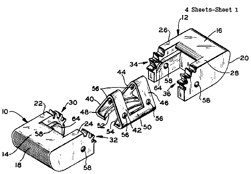
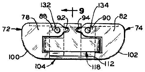
BRIEF DESCRIPTION OF THE DRAWINGS FIG. 1 is an exploded perspective view of a cutting device embodying this invention;
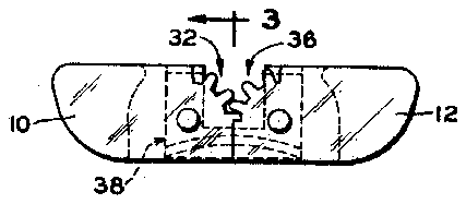
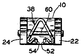
FIG. 2 is a front elevation view of the cutting device shown in FIG. 1;
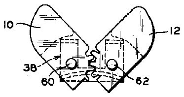
FIG. 3 is a cross sectional view taken along lines 3-3 of FIG. 2;
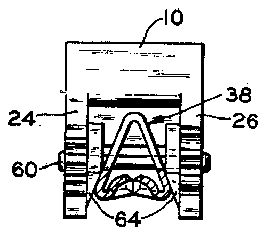
FIG. 4 is a front elevation view of the cutting device in its actuated cutting position;
7 FIG. 5 is a cross sectional view of the cutting device taken along the lines 5-5 of FIG. 4;
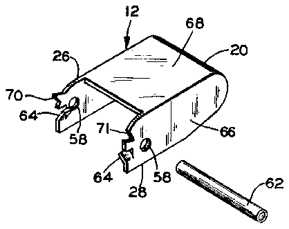
FIG. 6 is an exploded perspective view of the cutting device encompassing this invention with the parts being of a stamped construction;
FIG. 7 is an exploded perspective view of another embodiment of this invention;
FIG. 8 is the front elevation of the embodiment of this invention shown in FIG. 7;
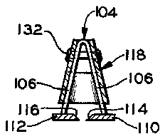
, FIG. 9 is a cross sectional view taken along lines 99 of FIG. 8;
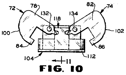
FIG. 10 is a front elevation view of the embodiment of the invention shown in FIG, 7 with the actuating members in the pivoted operating position;
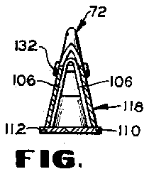
FIG. 11 is a cross sectional view taken along lines 11- 11 of FIG. 10;
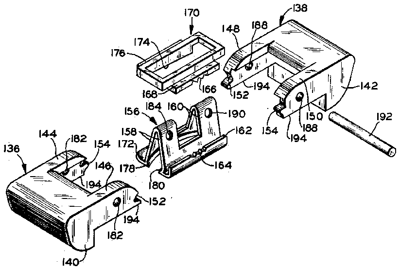
FIG. 12 is an exploded perspective view of a still further embodiment of this invention showing a second cutting surface on one side of the cam ring and cutting spring and a gripping means on the other side of the cam ring and cutting spring;
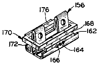
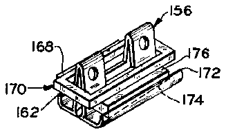
FIG. 13 is a perspective view of the cam ring and cutting spring of FIG. 12 in assembled position and par- 3 ticularly disclosing the gripping means associated therewith;
FIG. 13A is a perspective view similar to FIG. 13 except that the assembly is rotated'360" to disclose the cooperating cutting surfaces on the cam ring and the cutting p FIG. 14 is an exploded perspective view of still another embodiment of this invention;
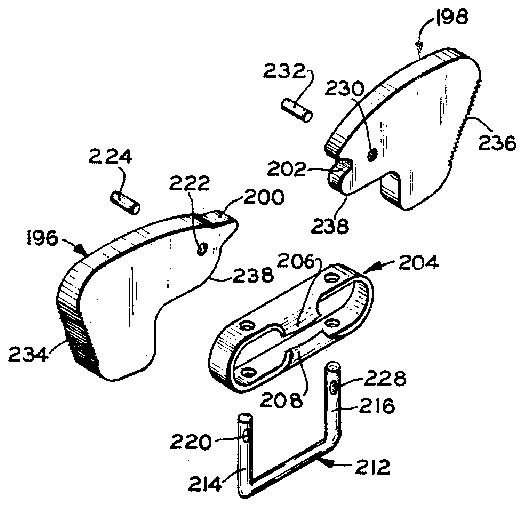
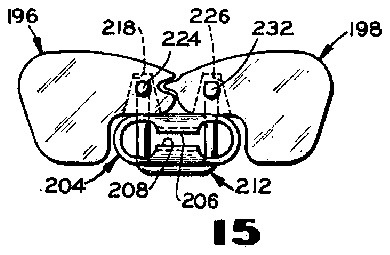
FIG. 15 is a front elevation view of the embodiment of this invention shown in FIG. 14;
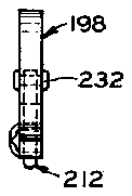
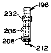
FIG. 16 is a cross sectional view taken along lines 1616 of FIG. 15;
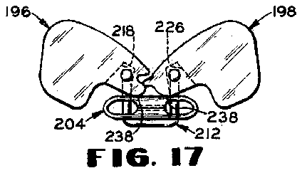
FIG. 17 is a front elevation view of the embodiment shown in FIG. 14 with the actuating members in the pivoted operating position; and
FIG. 18 is a cross sectional view taken along lines 1818 of FIG. 17.
DESCRIPTION OF THE PREFERRED EMBODIMENTS First embodiment (FIGS. l-)
Referring more particularly to the drawings, a cutting device as shown in FIG. 1 comprises basically three parts. Actuating members and 12 are one and the same type of part. Each actuating member 10 and 12 has a base portion 14 and 16 having a suitable curvature and serrations 18 and 20 on the ends thereof to facilitate gripping of the actuating members with the fingers and the thumb. The base portions 14 and 16 are provided with'bifurcations 22, 2 4 and 26, 28 respectively. The bifurcations are each provided with a plurality of gear teeth 30, 32, 34, and 36 which are adapted to form mating pairs when the cutting device is assembled as shown in FIG. 2.
The bifurcations 22, 24 and 26, 28 are spaced apart sufiiciently to accommodate a spring member 38 therebetween. The spring member 38 is generally of triangular configuration with the central portion thereof cut away. Accordingly, the spring member comprises two integral legs 40 and 42 angularly positioned with respect to each other on one side, and two integral legs 44 and 46 positioned angularly with respect to each other on the other side. The legs 40 and 44 are positioned in the same plane and are connected by an integral base section 48. Likewise, the legs 42 and 46 extend in the same plane and are connected by an integral base section 50. The base sections 48 and 50 each are bent inwardly toward each other and have the inner edge thereof suitably honed along the length to form cutting surfaces 52 and 54.
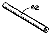
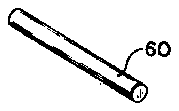
Thus, it is apparent that the spring member 38 is wider at the base than it is at its upper portion and that when pressure is applied upon the side of the spring member adjacent the base, the cutting surfaces 52 and 54will be moved toward each other against the resiliency of the spring legs 40, 42 and 44, 46. The lower portion of each of the spring legs 40, 42 and 44, 46 is provided with an aperture 56 extending therethrough. Apertures 58 are also provided in each of the bifurcations 22, 24 and 26, 28 of the actuating members. The apertures 56 and 58 are aligned so that the legs 40 and 42 of the spring member are positioned between the bifurcations 22 and 24 and receive a cylindrical pin 60. A similar cylindrical pin 62 extends through the aligned apertures 56 and 58 so that the legs 44 and 46 of the spring member 38 are accommodated between the bifurcations 26 and 28 of actuating member 12. The ends of the pins 60 and 62 are then secured against axial movement in any suitable manner, such as that shown in FIGS. 3 and 5. It is now apparent that the actuating members 10 and 12 are each secured to one side of the spring member 38 with the gear teeth 30, 34 and 32, 36 in engagement. Thus, the actuating members 10 and 12 are free to pivot vertically upwardly about the pins 60 and 62 which are held in the spring member 38.
Cam means is provided in association with the actuating members 10 and 12 and the spring member 38 to move the cutting surfaces 52 and 54 of the spring member together upon vertical pivotal movement of the actuating members. More particularly, the inner surfaces 64 of the bifurcations 22, 24, 26 and 28 are each provided with a curvature such that the surface above the apertures 58 extends inwardly with respect to the surface of the bifurcations below the apertures 5 8.
In operation of the embodiment shown in FIG. 1, the cutting device is carried in the position shown in FIG. .2 with the cutting surfaces 52 and 54 of the spring member 38 totally encompassed by the actuating members 10 and 12 and thus not subject to tearing the pocket of the user. It should be noted that when the cutting device is taken from the pocket and placed in the hand it is immediately read for use. There is no pivotal movement or cocking of the device required to place it in position for operation. The actuating members 10 and 12 are grasped along the serrations 16 and 18 between the thumb and fingers of the user and the fingernail to be clipped is placed between the cutting surfaces 52 and 54. Upon squeezing the thumb and the fingers, the actuating members 10 and 12 pivot upwardly in a vertical direction about pins 60 and 62. As the base portions 14 and 16 move upwardly, the cam surfaces 64 on the internal surface of the bifurcations pivot downwardly and provide pressure along the legs 40, 42, 44 and 46 to squeeze the base of the spring member 38 together so that the cutting surfaces 52 and 54 can perform the clipping operation. It should be noted that the gear teeth 30, 32, 34, and 36 being engaged in pairs, force the actuating members 10 and 12 to move upwardly an equal arcuate distance thus insuring that the cam surfaces 64 on each of the bifurcations provide an equal force on the legs of the spring member 38.
When the thumb and the fingers are released the actuating members 10 and 12 pivot downwardly from the position shown in FIG. 4 and return to the position shown in FIG. 2. Again, the cutting surfaces 52 and 54 are housed within the actuating members to facilitate carrymg.
Second embodiment (FIG. 6)
Referring now to the second embodiment'of the invention, where like parts will be given like reference numerals to that embodiment shown in FIGS. 1 through 5. The embodiment of the invention shown in FIG. 6 is very similar to that shown in FIGS. 1 through 5 but is constructed of stamped parts rather than the castings as shown in the first embodiment. More particularly, actuating members 10 and 12 are provided with side walls 66 and a top wall 68 which terminates in a curved over portion having serrations 18 and 20 for gripping purposes. Bifurcations 22, 24 and 26, 28 are provided on the actuating members 10 and 12. A single geartooth 70 is provided on bifurcations 24 and 26 and a single depression 71 is provided in each bifurcation 22 and 28. Beneath the gear tooth 70 and the depression 71 on each bifurcation is a cut and bent-in portion forming a cam surface 64.
A spring member 38 having a truncated cone shape is provided with bent over portions on the base thereof extending toward each other and terminating in honed cutting surfaces 52 and 54. Four apertures 56 are provided in the spring member 38 and two are aligned with apertures 58 in bifurcations 22 and 24 while the other two are aligned with apertures 58 in the bifurcations 26 and 28. A pair of cylindrical pins 60 and 62 extend through the apertures and are secured against axial movement by any suitable means.
The operation of the embodiment shown in FIG. 6 is similar to that as shown in the previous embodiment. Vertical pivotal movement of the actuating members 10 and 12 cause the cam surfaces 64 to apply pressure down the surface of the spring member 38 at four points to force the cutting surfaces 52 and 54 together. The single gear tooth connection between the mating bifurcations insures that an equal force distribution is provided.
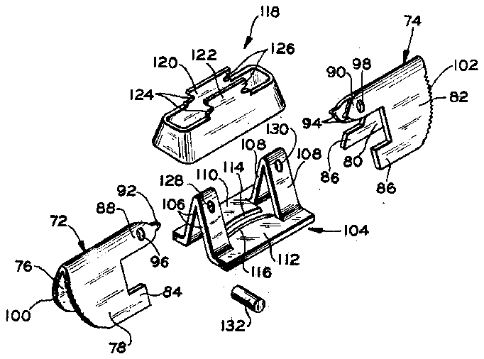
Third embodiment (FIGS. 7-11) Referring now more particularly to the embodiment of the invention shown in FIGS. 71l, a pair of like actuating members 72 and 74 are provided of stamped construction. Each of the actuating members is composed of two side sections 76, 78 and 80, 82 respectively. The side sections 76 and 80 are angularly disposed with respect to their integral side sections 78 and 82 with the side sections being joined solely by the creased top. The actuating members 72 and 74 are each provided with a pair of feet 84 and 86, respectively, which form the base of the actuating members.
Head portions 88 and 90 extend forwardly from the top of the actuating members 72 and 74 and each terminate in a pair of tooth like projections 92 and 94. Each head portion 88 and 90 is provided with a pair of apertures or eyes 96 and 98 while the back portions of the actuating members 72 and 74 have serrations 100 and 102 to facilitate gripping thereof.
Spring means in the form of a generally flat base with a pair of upward extending steeples is adapted to be positioned between the actuating members 72 and 74. More particularly, the spring member indicated generally at 104 has upwardly angularly extending integrally formed legs 106 and similar legs 108 spaced therefrom. The legs 106 and 108 are integrally connected at their bottom by base sections 110 and 112 which extend between the legs. The base sections 110 and 112 terminate on their inwardly extending portions in honed cutting edges or surfaces 114 and 116. The base sections 110 and 112 also extend outwardly from the legs 106 to provide flared stops for a cam ring 118 now to be described.
The cam ring 118 is of generally rectangular boxshaped construction which is adapted to be seated over the legs 106 and 108 of the spring member. The internal dimensions of the cam ring 118 are such that it may freely fit over the legs 106 and 108 of the spring member for a portion of the height of the legs. However, the base of the legs 106 and 108 are normally separated a greater distance than the internal dimension of the box like cam ring so that when the cam ring is forced to its lower position with the bottom surface engaging the outwardly extending flared base of the spring member, the spring legs 106 and 108 are squeezed together forcing the cutting surfaces 114 and 116 toward each other.
To effect upward and downward movement of the cam ring 118, towers 120 and 122 extend upwardly from the side walls of the cam ring and each is provided with depressions 124 and 126 on opposite sides thereof to receive the tooth-like projections 92 and 94 of the actuating members 72 and 74.
To secure the actuating members 72 and 74 to the spring member 104 while permitting vertical pivotal movement of the actuating members, apertures 128 and 130 are provided in spring legs 106 and 108 adjacent the upper portion thereof and are aligned with eyes 96 and '98 of the actuating members 72 and 74 respectively. Pin means 132 and 134 extend through the aligned apertures and are suitably secured against axial movement.
In operation, the cutting device is normally carried in the position shown in FIG. 8 wherein the spring member 104 and the cam ring 118 are positioned between the actuating members 72 and 74 with the cutting surfaces 114 and 116 completely shielded. When the cutting device is placed between the thumb and the fingers of the user it is immediately ready for use to clip the fingernail or other object placed between the cutting surfaces 114 and 116. The user merely squeezes the actuating members 72 and 74 along the serrations 100 and 102 to cause vertical pivotal movement of the outer ends thereof. Such vertical pivotal movement causes the tooth-like projections 92 and 94 extending from the head of the actuating members to force the cam ring 118 downwardly over the spring legs 106 and 108 against the bias thereof to move the cutting surfaces 114 and 116 toward each other to perform a cutting operation. Upon release of pressure on the actuating members 72 and 74, the resiliency of the spring legs 106 and 108 causes the cam ring 118 to move to its upward position thus returning the actuating members from the position shown in FIG. 10 to the original position shown in FIG. 8. From the foregoing it is apparent that the actuating members 72 and 74 are, in effect, geared together through their connection with the cam ring depressions 124 and 126 causing equal arcuate movement of the actuating members and a corresponding balanced downward movement of the cam ring to provide equal force distribution on the spring legs 106 and 108.
Fourth embodiment (FIGS. 12 and 13) Referring now more particularly to the embodiment of the invention shown in FIGS. 12 and 13, a pair of like actuating members 136 and 138 are provided with a contoured back surface having serrations 140 and 142 for gripping purposes. A pair of parallel protruding head portions or bifurcations 144 and 146 extend from the actuating member 136 while similar bifurcations 148 and 150 protrude from the actuating member 138. The terminal portion of bifurcations 146 and 148 are identical with each having a depression 152 whereas the bifurcations 144 and 150 terminate in tooth-like projections 154. Opposite projections 154 and depressions 152 are adapted to be received in mating engagement.
A spring member indicated generally at 156 is adapted to be accommodated between the bifurcations of the actuating members. More particularly, the spring member 156 is an integrally formed member having upwardly extending angularly positioned paired legs 158 and 160 spaced apart from each other, The legs 158 and 160 are connected by a base portion which has an outwardly flared upwardly extending horizontal shoulder 162 on one side of the legs. Approximately midway between the ends of the shoulder 162 vise-like teeth 164 are provided. The teeth 164 are adapted to cooperate with teeth 166 provided on the bottom of a cam surface 168. of a cam ring indicated generally at 170.
On the other side of the spring member 156 the legs 158 and 160 are also connected by a base portion which is flared outwardly and bent upwardly but in this case a honed cutting surface 172 is provided along the terminal edge. The cutting surface 172 cooperates with a cutting surface 174 provided on the bottom edge of a cam surface 176 provided on the other side of cam ring 170.
The cam ring is of rectangular configuration and has the previously described cam surfaces 168 and 176 secured along the sides thereof. The cam ring has internal dimensions such that it may be freely fitted over the legs 158 and 160 of the spring member 156. However, the legs 158 and 160 are separated at their base a distance greater than the internal dimension of the cam ring 170. Accordingly, when the cam ring is pressed downwardly over the legs of the spring member, the bottom portion of the legs are moved toward each other and cutting surfaces 178 and 180 provided on the base section of the spring member between the legs are moved to-' ward each other. At the same time, the vise-like teeth 164 on the spring member and 166 on the under surface of the cam ring come into engagement. Simultaneously, the cutting surface 172 extending upwardly from the spring member and the cutting surface 174 on the cam ring 170 cooperate to perform a shearing operation.
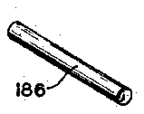
To secure the actuating member 136 to the spring member 156, eyes 182 are provided in bifurcations 144 and 146 and are aligned with apertures 184 provided in the upper portion of spring legs 158. A pin 186 extends through the aligned apertures and eyes and is secured against axial movement. The actuating member 138 is iimilarly secured to the spring member 156. To this end, :yes 188 are provided in bifurcations 148 and 150 and rre aligned with apertures 190 provided in the upper por- 11011 of spring legs 160. A pin 192 extends through the aligned apertures and is suitably secured against axial novement. When the actuating members 136 and 138 are :hus secured to the spring member 156, the teeth and iepressions 152 and 154 provided on the bifurcations :ome into mating engagement.
In operation, the cutting device is placed between the humb and the fingers of the hand and squeezing causes vertical pivotal movement of the actuating members 136 1nd 138 about the pins 186 and 192. At the same time, ;he forward ends of the actuating members pivot down wardly and cam surfaces 194 provided on hte under surface of the bifurcations bear against the cam surfaces [68 and 176 on the cam ring 170 to force the same downwardly and cam surfaces 194 provided on the under sur- .ower portion of the legs 158 and 160an> together causing :he cutting surfaces 178 and 180 on the base of the ipring member to perform a cutting operation. Additionrlly, a cutting operation is performed by cooperation of be cutting surface 172 on the flared portion of the spring and the cutting surface 174 provided along the side of :he cam ring upon downward movement thereof.
Furthermore, the vise-like teeth 164 on the spring mem- 361 and 166 on the cam ring are moved into engagement :hus providing a gripping action upon any object placed :herebetween. Since the bifurcations of the actuating memaers 136 and 138 are geared together, the actuating mem- )GIS pivot an equal arcuate distance and provide a )alanced downward pressure on the cam ring to, in turn, nsure the appropriate cutting operation.
Fifth embodiment (FIGS. 14-18) In this embodiment actuating members 196 and 198 are of generally pistol-like configuration. The actuating nembers are similar except that the end of the barrel por- :ion of the actuating members vary slightly. The actuating nember 196 is provided with a tooth-like projection 200 which is adapted to be received in a depression 202 prolided on the end of the actuating member 198.
A spring ring 204 somewhat elliptical in configuration s adapted to be positioned beneath the barrel sections of :he actuating members 196 and 198. Curved tabs extend nwardly from one side of the spring ring and terminate In honed cutting surfaces 206 and 208. The spring ring 204 has four apertures 210 extending therethrough. A U-shaped rod 212 has one leg 214 extending through two )f the apertures in the spring ring while the other leg 216 :xtends through the other two apertures of the spring ring. The leg 214 of the U-shaped rod extends into a lrilled recess 218 in the under surface of the barrel portion of the actuating member 196 and has an eye 220 which is aligned with an eye 222 in the actuating member. A pin 224 extends through the aligned eyes and is secured against axial movement. The other leg 216 of the U-shaped rod extends into a drilled recess 226 provided in the under surface of actuating member 198 and has an eye 2.28 which is aligned with an eye 230 provided in the actuating member. A pin 232 extends through the aligned eyes and is secured against axial movement.
In operation, the cutting device is placed between the thumb and the fingers which grasp the serrations 234 on the actuating member 196 and the serrations 236 on the actuating member 198. When the hand is squeezed, the actuating members pivot vertically upward about pins 224 and 232. Thus, the forward ends of the actuating members pivot arcuately downwardly so that cam surfaces 238 provided on the under surface of the barrel portion of the actuating members apply pressure against the cam surfaces of spring ring 204. Accordingly, the spring ring 204 is compressed from the position shown in FIG. 15 to that shown in FIG. 17 wherein the cutting surfaces 206 and 208 are brought into engagement to perform the cutting operation. Upon release of the actuating members 196 and 198, the resiliency of the spring ring 204 forces the actuating members to their original position as shown in FIG. 15. As with the other embodiments of this invention, the geared connection between the actuating members 196 and 198 insures a balanced force distribution on the spring ring 204 to insure a proper cutting operation.
In summary, a simple compact cutting device has been provided which may be carried in the operating position ready for use while at the same time the cutting surfaces are not exposed so as to be a hazard to the user. Many of the parts previously described such as the paired actuating members in most embodiments are the exact same structures which can thus be made from the same die or by using the same stamping operation.
While five embodiments of this invention have been shown and described, it is apparent from the foregoing that there may be many variations in the structure and operation without departing from the scope of this invention as defined in the following claims.
What is claimed is:
1. A cutting device comprising (a) a first actuating means, (b) a second actuating means, (c) spring surfaces having cutting means associated therewith, (d) means connecting said first and second actuating means to said spring means while permitting pivotal movement with respect thereto, (e) means drivingly interconnecting said first and second actuating means for movement in unison, (f) cam means associated with said first and second actuating means and said spring means whereby pivotal movement of said actuating means effects movement of said cutting surfaces toward each other to perform a cutting operation.
2. The combination of claim 1 wherein said first and second actuating means pivot in one plane whereas said cutting surfaces move toward each other in a plane perpendicular to said one plane.
3. The combination of claim 1 wherein said first and second actuating means are connected for pivotal movement with respect to each other whereby a pivotal movement of said first actuating means produces an equal and opposite pivotal movement of said second actuating means and vice versa.
4. The combination of claim 3 wherein said first and second actuating means are directly geared together.
5. The combination of claim 3 wherein said first and second actuating means are geared together each through a pivotal connection with said cam means.
6. The combination of claim 3 wherein said first and second actuating means each have bifurcations Which surround a portion of said spring means and said means connecting said first and second actuating means to said spring means comprises a pair of pins each extending through the bifurcations of one of said actuating means and said spring means.
7. The combination of claim 6 wherein gear means are provided on the ends of said bifurcations and said gear means on said first and second actuating means are in mating engagement.
8. The combination of claim 7 wherein said spring means is wider at the bottom than the top and said cam means extends inwardly from the inner surface of said bifurcations for engagement with said spring means upon pivotal movement of said first and second actuating means to move said cutting surfaces of said spring means toward each other.
9. The combination of claim 1 wherein said cam means includes a cam ring movable upon pivotal movement of said first and second actuating means, and said spring means is wider at the bottom than the top whereby movement of said cam ring down said spring means effects movement of the bottom portion of said spring means together against the bias of the spring means to move said cutting surfaces toward each other.
10. The combination of claim 9 wherein said first and second actuating means each have gear means in engagement with each other and cam means engageable with said cam ring upon pivotal movement of said gear means.
11. The combination of claim 9 wherein said first and second actuating means each have a projection extending inwardly mating with a portion of said cam ring whereby said first and second actuating means are geared together through said cam portion and said cam ring is moved downwardly by said first and second actuating means projections upon pivotal movement of said first and second actuating means.
12. The combination of claim 9 wherein the bottom portion of said spring means has a flared out portion, and the bottom portion of said cam ring has means flared outwardly whereby said flared out portions are firmly pressed together upon pivotal movement of said first and second actuating means to form a gripping means.
13. The combination of claim 9 wherein the bottom portion of said spring means has a cutting surface extending therefrom, and said cam ring has a cutting surface which cooperates with said extending cutting surface to perform a cutting operation upon pivotal movement of said first and second actuating means.
14. The combination of claim 1 wherein said cam means is a surface on said first and second actuating means engageable with said spring means to.compress the same to perform a cutting operation.
15. The combination of claim 14 wherein said spring means is a ring shaped member having apertures therein, and a U-shaped member extends through said apertures with one leg thereof connected to each of said actuating means while permitting pivotal movement thereof.
16. The combination of claim 15 wherein said actuating means are connected for pivotal movement with respect to each other whereby pivotal movement of one of said actuating means produces an equal and opposite pivotal movement of the other of said actuating means.
References Cited UNITED STATES PATENTS 806,037span> 11/1905 Wilcox 3028 FOREIGN PATENTS 8,933 4/1908 Great Britain.
OTHELL M. SIMPSON, Primary Examiner G. F. GRAFEL, Assistant Examiner UNITED" STATE PATENT OFFICE CERTIFICATE OF CORRECTION Patent No. 3,497,956 March 3, 1970 Thomas S. Bowers It is certified that error appears in the above identified patent and that said Letters Patent are hereby corrected as shown below:
Column 8 line 24, "surfaces" should read means line 25, means'; flrst occurrence, should read surfaces Signed and sealed this 29th day of December 1970.
(SEAL) Attest:
WILLIAM E. SCHUYLER, JR.
Commissioner of Patents Edward M. Fletcher, Jr.
Attesting Officer
