

- 2references cited united states patents
- 10spring leaves
- 12spring leaves
- 14flanges
- 15adjustable actuating assembly
- 16cutting edges
- 18actuating lever
- 20stud
- 24slot
- 26bar
- 28lower member
- 30threaded shank
- 32upper member
- 34conventional head
- 36opening
- 38upset portion
- 50boss
- 2439,312 2/ 1965 fink 30-28 foreign patents
- 566references cited united states patents
- 695references cited united states patents
- 9019,312 2/ 1965 fink 30-28 foreign patents
Abstract
DISCLOSED HEREIN IS A CLIPPER HAVING A PAIR OF SPRING LEAVES JOINED AT ONE END WITH CURVED SHARPENED COMPLEMENTARY EDGES AT THE OTHER END AND AN ADJUSTABLE STUD INTERCONNECTING THE SPRING LEAVES TO SELECTIVELY VARY THE DISTANCE BETWEEN THE SHARPENED EDGES, THE STUD HAVING A HOOK-SHAPED UPPER END TO RECEIVE THE CROSS BAR OF AN ACTUATING LEVER HAVING AN UPSET CENTRAL PORTION BEARING ON ONE OF THE LEAF SPRINGS WHEREBY ACTUATION OF THE LEVER WILL OPEN AND CLOSE THE SHARPENED EDGES.
Description
Jan. 19, 1971 JURENA 3,555,675
ADJUSTABLE FINGERNAIL AND TOENAIL CLIPPER Filed June 10, 1968 United States Patent Office 3,555,675 ADJUSTABLE FIN GERNAIL AND TOENAIL CLIPPER Prokop J. Jurena, 5430 W. Forest Home Ave., Milwaukee, Wis. 53220 Filed June 10, 1968, Ser. No. 735,830 Int. Cl. A45d 29/02 US. CI. 3028 7 "Claims ABSTRACT OF THE DISCLOSURE BACKGROUND OF THE INVENTION Fingernail and toenail clippers are conventionally made in a variety of sizes with an opening between the cutting edges of the clipper to accommodate nails of various thicknesses and shapes. In particular, it is desirable to have a clipper for every application which has an opening between the cutting edges just a tiny fraction of an inch more than the nail to be cut, regardless of the thickness or shape of the nail. In this manner the nail is cut more efiiciently, and skin next to the nail is readily excluded from the opening or space between the blades or cutting edges.
SUMMARY OF THE INVENTION The invention disclosed herein provides a conventional clipper which is arranged to be adjusted by the user to accommodate fingernails or toenails, whereby a single clipper can be used to fulfill all clipping needs. More particularly, the clipper includes a pair of spring leaves joined at one end and having curved sharpened complementary edges at the other end with an adjustable actuating assembly connected to compress the spring leaves and to adjust the distance between the sharpened edges. The distance between the cutting edges on the leaf springs is adjustable to receive fingernails or toenails of various configurations, whether or not they are smooth, and regardless of their thickness. The spring leaves are constructed heavily enough to be capable of clipping either fingernails or toenails. Although only two embodiments of the invention are shown and described, other embodiments are present without departing from the scope of my invention, which is defined by the claims.
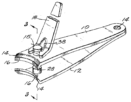
FIG. 1 is a perspective view of the device of my invention.
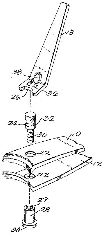
FIG. 2 is an exploded view of the device of my invention.
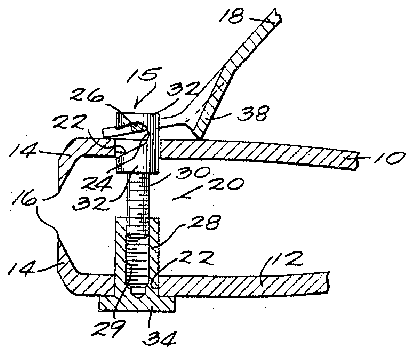
FIG. 3 is a cross-sectional view taken on line 3-3 of FIG. 1.
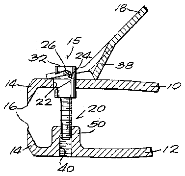
FIG. 4 is a view like that of FIG. 3 but showing a modified form of my device.
DESCRIPTION OF THE INVENTION Although the disclosure hereof is detailed and exact to enable those skilled in the art to practice the invention, the physical embodiments herein disclosed merely exemplify the invention which may be embodied in other specific structure. The scope of the invention is defined in the claims appended hereto.
3,555,675. Patented Jan. 19, 1971 As shown in the drawing the clipper of my invention comprises a pair of heavy spring leaves 10 and 12 joined at one end by means of an eyelet 14 to form a normally open tongs. The free end of each spring leaf is bent toward the other spring leaf to form flanges 14 which are curved to conform to the shape of the edge of a fingernail or toenail. :Each of flanges 14 terminates in a beveled cutting edge 16 which is so sharpened that when the leaves are compressed to bring the cutting edges together the sharpened edges 16 meet along their entire length.
The leaves 10 and 12 are moved into cuttingengagement to cut a fingernail or toenail by means of an adjustable actuating assembly 15 which includes a lever 18 pivotally connected to the spring leaves 10 and 12 by means of an adjustable cylindrical stud 20. More specifically, the spring leaves 10 and 12 are provided with aligned holes 22 centered laterally of the leaves and located just behind the curved flanges 14. The cylindrical stud 20 extends through the holes 22 in the spring leaves 10 and 12 with one end of the stud 20 connected to one of the spring leaves. In a conventional clipper this would be accomplished by putting a head on the other end of the cylindrical stud. This connection is modified in accordance with my invention to provide a stud having a variable height so that the distance between the cutting edges 16 may be adjusted. As shown in FIG. 3 the stud 20 consists of a lower portion or member 28 having a tapped bore 29 to receive a threaded shank 30 provided on the upper portion or member 32. The lower member 28 has a conventional head 34 to apply reaction force to the lower spring leaf 12 when the clipper is to be closed. Because of the threaded connection between the upper member 32 and the lower member 28 of the stud, the len th of the stud may be changed simply by rotating the upper member 32 of the stud relative to the lower member 28.
The actuating lever 18 is provided with an opening 36 to receive the upper member 32 of the stud 20 with a bar 26 across the opening 36 to engage a slot 24 in the upper member 32. An upset portion 38 is provided immediately adjacent the opening 36 to engage the surface of the spring leaf 10 adjacent to the hole 22. The remaining portion or free end of the actuating lever is adapted to be pressed by the user to cause the upset portion 38 to bear on the spring leaf 10 and compress the spring leaves 10 and 12.
Adjustment of the distance between the cutting edges 16 is accomplished by rotating the actuating lever 18 about the stud 20 to turn the upper member 32 relative to the lower member 28. Depending on the direction of rotation of the actuating lever, the upper member 32 will be screwed into or out of the lower member 28. Although the lower member 28 of the stud is shown round, it can be made in a shape other than round, i.e., square, with a correspondingly shaped hole to hold the lower member 28 fixed when the upper member is rotated. This adjustment of the length of the stud 20 makes it possible to vary the distance between the cutting edges to correctly fit thin, thick or irregular shaped toenails or fingernails.
In FIG. 4 a modified stud is shown in which the lower member is in the form of a boss 50 welded to the spring leaf 12 in alignment with the location of the hole 22 in spring leaf 10. The metal of the lower spring leaf 12 could also be upset toward the upper spring leaf 10 to form the threaded section.
What is claimed is:
1. A clipper comprising a pair of spring leaves joined at one end and having complementary cutting edges at the other end, and means adapted to move the opposed cutting edges into edge-contact cutting engagement including means to adjustably fix the initial distance between the cutting edges comprising an upper member adjustable in height in respect to a lower member.
2. A clipper according to claim 1 wherein said upper member includes a threaded shank and said lower member includes a threaded bore, said upper and lower members together comprising a stud.
3. A clipper according to claim 1 wherein said lower member comprises a boss secured to one of the spring leaves.
4. A clipper according to claim 1 wherein said lower member is fixed relative to a said spring leaf.
5. A clipper according to claim 1 wherein said means adapted to move the spring leaves includes an actuating lever pivotally secured to said means to adjustably fix said distance.
6. A clipper according to claim 1 wherein said upper member includes a threaded shank and 'said lower member includes a threaded bore, said upper and lower members together comprising a stud, said lower member comprising a boss secured to one of the spring leaves, said means adapted to move the spring leaves including an actuating lever pivotally secured to the means to adjustably fix said distance.
7. A clipper according to claim 1 wherein said upper member includes a threaded shank and said lower member includes a threaded bore, said upper and lower members together comprising a stud, said lower member being fixed relative to a said spring leaf, said means adapted to move the spring leaves including an actuating lever pivotally secured to the means to adjustably fix said distance.
References Cited UNITED STATES PATENTS 2,566,695 9/1951 Cormier 81-43 3,169,312 2/ 1965 Fink 30-28 FOREIGN PATENTS 243,901 12/1925 Great Britain.
ROBERT C. RIORDON, Primary Examiner G. F. GRAFEL, Assistant Examiner


