- 1uhekq states patent hedu
- 10clipper
- 11body member
- 12body
- 14thumb-depression access tojaw
- 16secured end
- 18cutting edge
- 19lever
- 20rivet
- 21sandoe et
- 22free end
- 24cavity
- 25opening
- 26tapering shallow bulge
- 27similarly tapering deeper bulge
- 29pocket
- 30edge
- 31body
- 34bulging wall
- 35further retaining lug
- 36finger-access opening
- 37opposed detents
- 40cavity
- 41tool
- 42folded u-shaped channel or case
- 43retaining-lug means
- 55plane
Abstract
The invention provides a novel combination of a nail clipper and molded plastic case or retaining body therefor, such that the clipper is available for ready use, apart from the body, by overcoming a retaining detent-engagement action between interfering parts of the body and clipper. The arrangement is such that the spring lever of the clipper serves as a clip, to resiliently hold the assembled clipper and body in a clothing or other pocket. In the form described, the body member is a hair comb, in which case, the lever of the clipper is the spring clip by which both grooming-tool functions are pocket-retained and readily available for use.
Description
UHEKQ States Patent Hedu 1 Jan. 23, 1973 [54] CLIPPER-COMBINED DEVICE Primary Examiner-Louis G. Mancene [75] Inventor. Jon Hedu, Watertown, Conn. Assistant Examiner j. O- Lever [73] Assignee: The W. E. Bassett Company, Derby, AttorneyNichol M. Sandoe et 21].
Conn. [22] Filed: Dec. 15, 1971 [57] ABSTRACT Appl. N0.: 208,107
The invention provides a novel combination of a nail clipper and molded plastic case or retaining body therefor, such that the clipper is available for ready use, apart from the body, by overcoming a retaining detent-engagement action between interfering parts of the body and clipper. The arrangement is such that the spring lever of the clipper serves as a clip, to resiliently hold the assembled clipper and body in a clothing or other pocket. 1n the form described, the body member is a hair comb, in which case, the lever of the clipper is the spring clip by which both grooming-tool functions are pocket-retained and readily available for use.
12 Claims, 6 Drawing Figures PATENTEUJANZS m1 3.712.311
INVENTOR \TO/Y HEA CLIPPER-COMBINED DEVICE The invention relates to pocket implements or tools, including grooming devices, such as nail clippers.
It is an object of the invention to provide an improved device of the character indicated, extending the utility thereof.
Another object is to provide a novel combined tool of the character indicated, providing selectively available multiple-tool functions.
A specific object is to provide a novel multiple-purpose tool including a nail clipper.
Another specific object is to provide a novel pocketclip function for a device of the character indicated.
Other objects and various further features of novelty and invention will be pointed out or will occur to those skilled in the art from a reading of the following specification, in conjunction with the accompanying drawings. In said drawings:
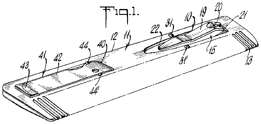
FIG. 1 is a view in perspective of an assembled clipper device of the invention;
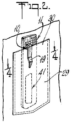
FIG. 2 is a simplified fragmentary view in perspective to show the device of FIG. 1, retained in a garment pocket;
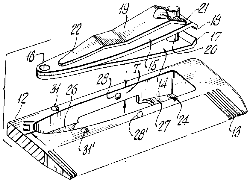
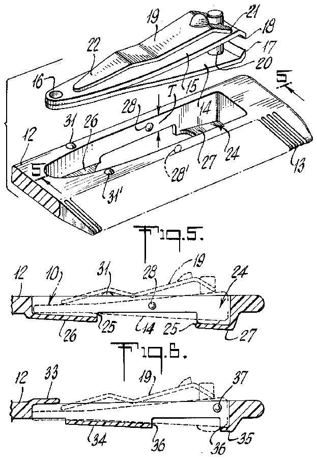
FIG. 3 is an exploded fragmentary view in perspective to illustrate the body member of FIG. 1, just prior to clipper assembly thereto;
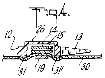
FIG. 4 is a sectional view at the plane 4-4 of FIG. 2;
FIG. 5 is a sectional view at the plane 55 of FIG. 3; and
FIG. 6 is a view similar to FIG. 5 to illustrate a modification.
The invention is shown in application to a combined tool wherein a finger-nail clipper 10 is removably retained in a body member 11 which is capable of performing a different tool function, namely a hair comb. The body member 11 is elongate along its back or body 12, and has plural comb teeth 13 extending transversely from one longitudinal edge. Body member 11 may be of suitable molded plastic material.
The nail clipper 10 may be of conventional configuration, comprising opposed stiffly compliant elongate jaw members 14-15, secured as by welding at one end (16) and formed with spaced cutting edges 17-18 at the other longitudinal end. A reversible actuating lever 19 is mounted against the outer face of the upper jaw, being compressionally pinned thereto by a headed rivet 20 which passes through aligned openings near the cutting endsof the jaw members. The actuating lever 19 is of generally arched contour and in the folded position shown, a foot contact exists at 21, at a location longitudinally intermediate the rivet 20 and cutting edge 18. Under this circumstance, the stiff spring action of jaws applies a turning moment to lever 19, resiliently loading the free end 22 thereof against the adjacent face ofjaw 15.
Near one longitudinal end, the body 12 is characterized by a cavity 24 which, as best shown in FIG. 3, is shaped and contoured generally in accordance with the planform of the jaws 14-15. Cavity 24 is shown fully open at the upper face of body 12 and is only partly open at the lower face; also as shown, the lower face is characterized by an outwardly bulging wall or walls, so accommodated to the profile of the clipper 10 that the inserted clipper is nested in cavity 24 with its folded lever 19 substantially adjacent the upper face of body 12 (as best seen in FIG. 1). The body 12 has a principal thickness T which appears at the cut-out 25 in the bulging lower wall or face of body 12. Thus, a tapering shallow bulge 26 defines the bottom wall of cavity 24 at the secured end 16 of the jaw members, and a similarly tapering deeper bulge 27 defines the bottom wall of the cavity at the cutting ends (17-18).
Snap-detent means coacts between clipper 10 and body 12 in the course of clipper assembly to cavity 24. As shown, a pair of opposed detent projections 28-28 (integral with body 12 and in the general longitudinal region of opening 25) extent toward each other to present detent interference with the side edges of jaws 14-15 in the course of such assembly. This relation is held pending disassembly, as by thumb-depression access tojaw 14 via the opening 25.
As noted above, the assembled clipper 10 and body 12 present lever 19 adjacent the upper face of body 12 (see FIG. 5), with the hinge point of lever 19 near the upper or cutting end of the assembly. Thus, the free end of lever 19 faces downwardly, and when the assembly is inserted into a pocket 29 (FIG. 2), as for example a coat pocket, the lever 19 will resiliently ride over and pinch the upper edge 30 of the pocket. If the detent-retained plane of the upper surface of jaw 15 (near end 16) is slightly below the upper face of body 12, then the pinch action by lever 19-will be laterally stabilized and self-centering, in that pocket edge 30 is caused to engage cavity side-wall edges which are in the pinch region; this centering action can be enhanced by provision of further integral grip projections 31-31 on opposite lateral sides of cavity 24 and in the indicated longitudinal region, as will be understood.
FIG. 6 shows a modification in which a retaining lug or lugs 33 is formed locally in the upper face of body 12 and at the secured-jaw end of the cavity 24, while the bulging wall 34 in the lower face of body 12 is longitudinally centrally located. A further retaining lug 35 in the lower face of body 12 projects to support the cutting ends of the jaws, leaving a finger-access opening 36 through which to dislodge the clipper; opposed detents 37 project toward each other to resiliently interfere with jaw insertion and removal. In this embodiment, the secured end 16 is first inserted under lug 33, and then the cutting end is snapped in place, to retain the inserted assembly.
The desired construction will be seen to achieve all stated objects, for the specific case of a clipper-andcomb combination. The combination of the clipper 10 with body 12 may also achieve still further tool combinations, with or without the comb feature 13. For example, as illustrated by FIG. 1, the lower part of body 12 may be formed with a second cavity 40 to insertably receive a further tool 41, the same being detachably held in place by lug and detent means analogous to that described for clipper 10. Thus, cavity 40 may be shaped in accordance with the planform of tool 41, shown as a knife-like tool with a pivoted blade or blades within a folded U-shaped channel or case 42. The lower face of body 31 may be bulbous as necessary to receive tool 41, and retaining-lug means 43 and detent means 44-44' at the upper face of body 12 may hold the assembled relation. It will be appreciated that for such assembly of the added tool 41, longitudinally spaced beneath clipper 10, the mass of tool 41 produces a pendulous stabilizing action to better preserve the vertical orientation of the entire assembly, from the edge 30 to which it is clip-pinched by means 19.
While the invention has been described in detail for the forms shown, it will be understood that modifications may be made without departing from the scope of the invention. And the term molded plastic," as used herein, will be understood to include other materials, such as hard rubber, suitable for the indicated purposes.
What is claimed is:
1. A pocket implement, comprising a molded-plastic body member in combination with a nail clipper; said body member having front and back faces and an article cavity open via at least one of said faces, and said nail clipper being removably positioned in said cavity; said clipper comprising opposed elongated stiffly complaint jaw members secured at one end and having opposed spaced cutting edges at the other end, an actuating lever alongside one of said jaw members, and rivet means extending through aligned openings of both jaw members near said other end and compressionally pinning one end of said lever to the other of said jaw members, said lever having an arched profile at its pinned end such that when folded against said one jaw member the concave side of said profile is adjacent said one jaw member, whereby the compliant action of said jaw members resiliently loads the other end of said lever against said one jaw member; said cavity conforming generally to the planform of said jaw members, and retaining means including a detent formation on one of said members, said retaining means establishing detent interference between said body member and one of said jaw members in the course of clipper insertion into said cavity, said lever being positioned adjacent the general plane of said front face when said clipper is detent-retained in said cavity.
2. The implement of claim 1, wherein said body member is elongate in the general direction of the elongation of said jaw members, the pinned end of said clipper when retained in the cavity being near one end of said body member, whereby said actuating lever may serve as a pocket clip to resiliently retain the assembled clipper and body member in upright orientation in a garment or the like pocket.
3. The implement of claim 2, wherein said front face includes outward pocket grip projections on opposite sides of the cavity alongside the free end of the lever when said clipper is assembled to said body member.
4. The implement of claim 1, wherein said back face is partly open to said cavity, whereby finger access through the latter opening enables clipper removal past the detent engagement.
5. The implement of claim 4, wherein the back face is of outwardly bulging contour at the cavity region, the partial opening being in said bulging contour.
6. The implement of claim 5, wherein the partial opening is located intermediate the longitudinal ends of the cavity.
7. The implement of claim 5, wherein the partial opening is located near the pinned end of said clipper.
8. The implement of claim 7, wherein the front face of said body member includes retaining-lug means overstanding a part of the cavity near the end which receives the secured end of said jaw members.
9. The implement of claim 1, wherein said detent formation is one of two like opposed projections integral with said body member and extending toward each other and overstanding parts of the lateral sides of the cavity.
10. The implement of claim 9, wherein said back face is partly open to said cavity and said detent projec-v tions are offset from said back face and longitudinally near the partly open region.
11. The implement of claim 2, in which said body member has a second article cavity longitudinally spaced from the first-mentioned cavity, a tool selectably receivable in and removable from said second cavity, and detent means on said body member engageable with said tool in the course of insertion thereof into said second cavity, whereby the mass of the tool provides pendulous stability for the assembled implement, when clipped to a pocket.
12. The implement of claim 1, wherein said body member includes comb teeth projecting generally transverse to the elongation axis of the cavity.


