- 2er 1,146,610 7/1915 altman 30/178 blades
- 7] references cited united states patents
- 10channels
- 11channels
- 13leg portions
- 14trunnions
- 15engaging openings
- 16cutting heads
- 17cutting heads
- 18springs
- 19springs
- 20concave portion
- 21cutting edge
- 22triangular portions
- 23concave portion
- 24cutting edge
- 25triangular portions
- 26member
- 27slots
- 28cooperating openings
- 31end walls
- 32rod
- 33coiled spring
- 34nut
- 35handle
- 36opening
- 37transverse portion
- 38pin
- 39slot
- 40aligned openings
- 41aligned openings
- 42portion
- 43short portion
- 837 drawing figures 716,876 12/1902 dunn
- 124means t-o adjust
- 128means t-o adjust 1,124,498 1/1915 millar
- 146clipper
- 411er 1,146,610 7/1915 altman 30/178 blades
- 498means t-o adjust
- 610clipper
Abstract
A clipper for shaping nails which includes a pair of cutting heads formed of resilient material and means for adjusting the curvature of the cutting heads.
Description
United States Patent 1191 [111 3,832,771 Morgan Sept. 3, 1974 [54] NAIL CLIPPER WITH MEANS T-O ADJUST 1,124,498 1/1915 Millar 128/309 THE CURVATURE OF THE CLIPPER 1,146,610pan></span> 7/1915 Altman 30/178 BLADES 2,411,016 11/1946 Azzara..... 83/696 2,816,552 12/1957 Hoffman.. 128/305 {76] Inventor: J. Robert Morgan, Palmer Hill Rd., 3,031,754 5/1962 Pocoski 30/28 Old Greenwich, Conn. 06870 [22] Filed: 1973 Primary Examiner-A1 Lawrence Smith [21] Appl. No.: 320,085 Assistant ExaminerGary L. Smith [52] US. Cl 30/28, 30/177, 30/178, 30/320, 83/696 51 Int. Cl A45d 29/02, B26b 19/04 [571 ABSTRACT [58] Field of Search 30/28, 175, 177, 178, 186,
30/229, 253, 320, 29; 128/2 B, 305, 309, A clipper for shaping nails which includes a pair of 311 313; 83/600, 696 cutting heads formed of resilient material and means for adjusting the curvature of the cutting heads. [56] References Cited UNITED STATES PATENTS 7 Claims, 7 Drawing Figures 716,876 12/1902 Dunn 83/696 NAIL CLIPPER WITH MEANS TO ADJUST THE CURVATURE OF THE CLIPPER BLADES This invention relates to nail clippers and more specifically to a novel and improved clipper having a cutting edge of sufficient length to clip substantially the entire width of the nail and which edge is adjustable so that a range of curvatures is provided to meet the desires of the user. Furthermore, the cutting edge may be scalloped or formed with other ornamental configurations.
Known nail clippers are generally formed of two elongated elements secured one to the other and having cooperating cutting edges of fixed configurations. The cutting edges are also relatively short so that only a portion of a nail can be clipped in a single operation and care must be exercised by the user to be certain that all nails are formed with substantially uniform curvatures and lengths. This invention overcomes the disadvantages of known clippers and not only enables an entire nail to be clipped at one time, but also ensures uniformity of length and curvature of each nail.
Another object of the invention resides in the provision of a novel and improved nail clipper wherein the curvature of the jaws or cutting heads is adjustable to meet the desires of the user and wherein the jaws are readily interchangeable to provide jaws of different ranges of curvature and ornamental configuration.
Still, another object of the invention resides in the provision of a novel and improved nail clipper for precisely shaping finger and toe nails and which is arranged and constructed to enable precise positioning of the cutting edges relative to the fingers or toes so that the nails will be uniformly shaped.
The nail clipper in accordance with the invention includes upper and lower tapered channels, a pair of concave jaws or heads slidably mounted on said channels and carrying cutting edges, the jaws being formed of a resilient material so that the degree of concavity can be modified by moving the jaws relative to the channels.
The above and other objects and advantages of the invention will become more apparent from the following description and accompanying drawings forming part of this application.
In the Drawings:
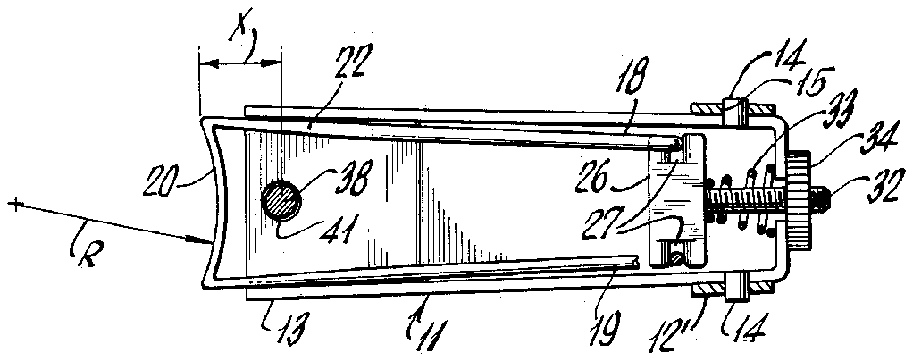
FIG. 1 is a cross-sectional view of the nail clipper in accordance with the invention,
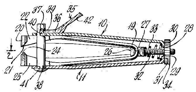
FIG. 2 is a cross-sectional view of FIG. 1 taken along the line 2-2 thereof,
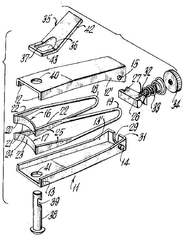
FIG. 3 is an exploded perspective view of the clipper shown in FIGS. 1 and 2,
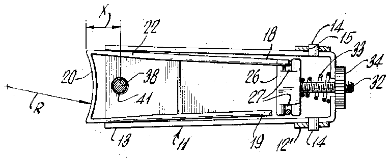
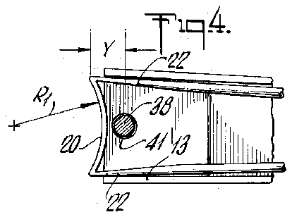
FIG. 4 is a fragmentary portion of the structure of FIG. 2 showing the cutting heads displaced to modify the curvature of the cutting edge,
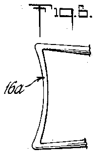
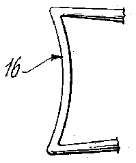
FIGS. 5 and 6 are enlarged plan views of cutting heads showing different configurations to obtain different types of curvatures, and
FIG. 7 shows one form of an ornamental cutting head configuration in accordance with the invention.
The nail clipper in accordance with the invention utilizes concave cutting heads or jaws which are adjustable to modify the curvature thereof and of a length sufficient to cut substantially the entire nail and thereby greatly facilitates uniform shaping of nails. One embodiment of a clipper for effecting these ends is shown in the drawings though it will become evident that other structures may be utilized to achieve the same objectives within the scope of the invention.
Referring now to the drawings, the clipper includes a pair of upper and lower channel members 10 and 11 with the legs 12 of the upper member extending downwardly and the legs 13 of the lower member extending upwardly. Both sets of legs taper substantially uniformly inwardly to the rear and terminate in parallel portions 12, 12' and 13, 13' with the portions 12, 12 overlapping the portions 13', 13'. The channel members are hinged one to the other by trunnions 14 extending from the leg portions 13, 13 and engaging openings 15 in the leg portions 12', 12'.
The cutting heads 16 and 17 are joined by U-shaped springs 18 and 19 which normally hold the cutting heads in spaced relationship as shown in FIGS. 1 and 3. More specifically, the cutting head 16 includes a concave portion 20 of resilient material and having a sharp cutting edge 21. The concave portion 20 is coupled to the upper legs of the springs 18 and 19 by triangular portions 22 which are spaced apart a distance approximately equal to the spacing between the inner surfaces of the outer ends of the legs 12, 12 of the channel 10 so that the triangular portions 22 will snugly fit the channel 10 with the cutting edge 21 extending well below the edges of the legs 12, 12. The cutting head 17 is arranged in a manner similar to the head 16 except that the cutting edge 24 on the concave portion 23 extends upwardly and the triangular portions 25 are coupled to the lower legs of the springs 18 and 19.
The cutting heads 16 and 17 are adjustably retained in position in the hinged channels 10 and 11 by a yokelike member 26 having slots 27 on the ends thereof for engaging the curved portions of the springs 18 and 19. A threaded rod 32 is secured to the member 26 and extends through cooperating openings 28 and 29 in the end walls 30 and 31 of the channels 10 and 11. A coiled spring 33 surrounds the rod 32 for urging the member 26 forwardly and a nut 34 threadably engages the rod for adjusting the position of the cutting members rela tive to the channels 10 and 11.
Operation of the clipper to open and close the cutting members is accomplished by a handle or lever 35 having an opening 36 therein to provide a relatively narrow transverse portion 37. A pin 38 having an undercut slot 39 formed therein extends through aligned openings 40 and 41 in channels 10 and 11 and the transverse portion 37 engages the slot 39. The pin 38 is retained in engagement with the handle 35 by the action of the springs 18 and 19 which urge the channel members outwardly. The handle 35 has an elongated portion 42 inclined upwardly from the channel 10 and a short portion 43 containing the opening 36. With this arrangement depression of the handle portion 42 will force the channels 10 and 11 together and close the cutting heads 16 and 17 to sever a nail disposed therebetween.
The clipper in accordance with the invention is intended to shape a finger or toe nail in one operation. Inasmuch as the nails have a natural curvature the cutting edges 21 and 24 have curvatures in the vertical plane as shown in FIGS. 1 and 3. For instance, in FIG. 3 it will be observed that the cutting edge 21 is concave in the vertical plane while the cutting edge 24 is convex and precisely mates with the cutting edge 21.
With the structure as described above, the curvature of the cutting heads 16 and 17 can be modified by displacing the cutters relative to the channels and 11 by tightening and loosening the nut 34. Because of the taper of the legs of the channels 10 and 11, as the cutting heads and associated springs 18 and 19 are drawn inwardly, the width of the cutting heads will decrease and thereby increase the curvature thereof. This action is shown in FIGS. 2 and 4. In FIG. 2 the cutting members are in an outer position with the forward portions of the cutting heads spaced from the center line of the pin 38 a distance X and the cutting heads have a radius R. In FIG. 4 the cutting heads have been moved inwardly so that the distance X has been reduced to the distance Y and the radius has been decreased to R1. In this way the radius of the cutting heads 16 and 17 can be readily adjusted to meet the desires of the user. Inasmuch as each cutting head has a length sufficient to cut an entire nail at one time, then by properly adjusting the cutting members and placing the end of the finger against one of the members with the nail disposed between the cutting heads, precise shaping of the nails can be accomplished. Furthermore, multiple sets of cutting heads can be provided in order to afford the user the choice of various ranges of curvatures.
In the embodiment of the invention thus far described, the cutting heads 16 and 17 have been illustrated as having substantially uniform thickness throughout the length and an enlarged view of the cutting blade 16 is shown in FIG. 5. In order to obtain a sharper curvature, the cutting members can be made somewhat thinner through the center as shown in the blade 16a in FIG. 6. It will be observed in this figure that the center of the blade is very much thinner than the edges so that as the blade is drawn into the associated channel member to increase the curvature, the center curvature of the blade will curve more sharply than the outer portions. If desired, the cutting members 16 and 17 may have any desired ornamental configuration such as a scalloped effect as shown on the blade 16b in FIG. 7. Although only one ornamental blade configuration is shown, it is apparent that any desired ornamental configuration may be utilized.
While only certain embodiments of the invention have been illustrated and described, it is apparent that alterations, modifications and changes may be made without departing from the true scope and spirit thereof as defined by the appended claims.
What is claimed is:
I. A clipper comprising a pair of cutting heads, curved cutting edges carried by said heads for movement one toward the other along a path for cutting material inserted therebetween and means carried by said clipper for flexing said cutter to modify the curvature of said cutting edges in a plane transversely of the path of said movement.
2. A clipper according to claim 1 wherein each cutting edge is formed integrally with its associated cutting head, said cutting heads are formed of a resilient material and the last said means includes a pair of opposing channels slidably receiving said cutting heads and means for adjustably positioning said heads in said channels.
3. A clipper according to claim 2 wherein each of said cutting heads vary in thickness from edge to edge to produce non-uniform curvature.
4. A clipper according to claim 2 wherein each of said channels is tapered in the longitudional direction so that movement of said cutting heads inwardly of said channels will increase the curvature of said heads.
5. A clipper according to claim 4 wherein said cutting heads are coupled to a pair of U-shaped springs with the ends of one spring being connected to each set of corresponding ends of the cutting heads.
6. A clipper according to claim 5 wherein said means for modifying the curvature of the cutting heads includes means engaging said springs and said channels for longitudinally positioning said heads relative to said channels.
7. A clipper according to claim 2 wherein each cutting head and associated cutting edges have a nonuniform configuration and curvature in the plane of the cutting edges.

