

- 10members
- 11members
- 12pro duoe cutting edges
- 13transverse pivot
- 14shoulder
- 15latch
- 16spring
- 18yoke
- 19lever
- 20cam portion
- 23notches
Description
E. T. MASON. FINGER on TOE NAIL GUTTER.
(No Model.)
H0. 504,601. Patented Sept. 5, 1893.
WITNESSES.
v MMWS A TTOHNE Y S.
UNITED STATES PATENT OFFICE.
EDMUND T. MASON, OF NEW YORK, N. Y.
FlNGER 0R TOE NAIL CUTTER.
SPECIFICATION forming part-of Letters Patent N 0. 504,601, dated September 5 1893.
Application filed March 11, 1893. Serial No. 465,542. (No model.)
To all whom it may concern.-
Be it known that I, EDMUND T. Mason, of New York city, in the county and State of New York, have invented a new and 1m.- proved Finger or Toe Nail Cutter, of which the following is a full, clear, and exact description.
My invention relates to an improvement in finger or toe-nail cutters, and has for its ob ject to provide a device which shall be simple, durable and economic, and by means of which a nail may not only be out but shaped while particles are being removed from it.
Another object of the invention is to provide a manicure device especially adapted for cutting nails, which will be compact and simple in its construction, and capable of being readily manipulated by onevhand, the device being made of such shape and capable of being so folded that it may be readily carried in the pocket or suspended from the watchchain, for example.
The invention consists in the, novel construction and combination of the several parts, as will be hereinafter fully set forth and pointed out in the claim.
Reference is to be had to the accompanying drawings forming a part of this specification, in which similar figures and letters of reference indicate corresponding parts in all-the views.
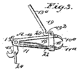
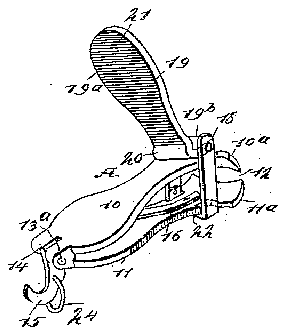
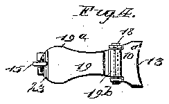
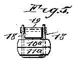
Figure 1 is a perspective view of the cutter, illustrating it in its open position. Fig. 2 is a central, vertical, longitudinal section through the cutter whenin its closed position. Fig. 3 is a side elevation of the cutter in its open position. Fig. 4. is a plan view thereof in its closed position; and Fig. 5 is a view of the cutting end of the cutter.
In carrying out the invention the body A of the device is somewhat of a viselike structure, comprising two members 10 and 11, preferably of the same general contour, which members are ordinarily made narrow near their central portions and at one end, the other end of each member being made quite wide, the wide portion forming the jaw, and the jaw of one member is designated as 10 while the jaw of the other member is designated as 11. The jaws are carried somewhat horizontally from the body in an inwardly direction, and the longitudinal edges of the jaws are sharpened so as to pro duoe cutting edges 12, while the longitudinal outer faces of the jaws at the cutting edges are decidedly concaved as illustrated at 13 in Fig. 4. The members 10, 11 are formed from a single plate of sheet metal bent into V or U shape so that when the free diverging ends of the members are pressed together the cutting edges will abut and when pressure is removed they will spring apart. The plate is slotted at its bend as shown at 14, and there provided with a transverse pivot 13 011 which is hung the hook latch 15. The heel of the latch is provided with a shoulder 15 which engages the free end of a plate spring 16 so as to be thrown outwardly thereby. The opposite end of the spring is secured'to the inner face of the member 11. The outer end of the member is provided with a yoke 18 between the side arms of which the member 10 is adapted to move freely. The yokecarries a pintle or pivot18 on which the cam lever 19 is pivoted asat 19 to engage the member 10 with its cam portion 20 and force the cutters together in the usual way. The under surface of the lever 19 has a file surface and its free end is provided with notches 23 for the point of the hook latch 19 to enter when the parts are in their closed position, see Fig. 2.
When the device is to be used pressure is applied to the lever 19 and the spring 16 will throw the latch out of engagement with it.
This spring retracted latch is a great improvement over a latch which has no spring and must be drawn away from the lever by hand or allowed to fall by gravity as in the latter instance rust or dirt would prevent such action.
24: is a suspension ring secured to the latch 15.
Having thus described my invention, I claim as new and desire to secure by Letters Patent- A finger nail cutter consisting in the integral diverging members 10, 11 provided at I I their free ends with cutters and formed of a to be engaged by, said latch, substantially as single piece slotted at its bend, the hook set iotth.w latch pivoted in the slot and provied at its heel with a shoulder 14, a spring 16 bearing- 5 on the said shoulder and throwing the latch Witnesses:
outwardlyand the operating cam lever for. WILLARD J. SLINKARD, forcing the members together and adapted W. A. ELDREDGE.
EDMUND T. MASON.