- 3cover
- 4threaded fastener
- 6slot
- 8cutter head
- 10blade
- 11shaft
- 12electric motor
- 14batteries
- 16bearing
- 18partition
- 20coupling member
- 21end fastener nut
- 24seat
- 26threaded fastener
- 30end section
- 32compartment
- 34switch
- 36electrical plug
- 38slide
- 40arrow
- 102housing
- 104main section
- 106cover
- 108cutter head
- 110cutter blade
- 112electric motor
- 114electrical batteries
- 120flexible tubular coupling
- 122bushing
- 124within compartment
- 130rib
- 132slots
- 134projections
- 140switch
- 180cover may be rotated
- 191british patent application
- 396british patent application
Abstract
A cutter device particularly useful for cutting fingernails and toenails includes a housing grippable by a user for holding and manipulating the device. A slot is formed in a conical end portion of the housing and is elongated in the circumferential direction for receiving a nail to be cut. A rotatable head having an outer conical surface is rotatably mounted within the conical end portion of the housing. A blade is fixed to the rotatable head and has a cutting edge extending substantially radially of the conical surface of the head and perpendicularly to the slot. A motor within the housing and coupled to the head rotates the head, and the blade fixed thereto, such that the cutting edge of the blade is rotated substantially perpendicularly to the direction of elongation of the slot and the nail received therein.
Description
RELATED APPLICATION
The present application is a continuation-in-part application of prior application Ser. No. 07/614,468, filed Nov. 16, 1990, which application is still pending.
FIELD AND BACKGROUND OF THE INVENTION
The present invention relates to a cutter device, and particularly to a cutter device useful for cutting fingernails or toenails.
At the present time, fingernails and toenails are usually cut by scissors, clippers, or a simple knife. However, such manually-operated implements are awkward or time-consuming to use, do not cut uniformly, may be difficult and/or even useless with respect to very thick nails, and/or may accidentally cut surrounding skin.
A number of motor-operated filing devices have been proposed, as illustrated for example in U.S. Pat. Nos. 4,896,684, 4,753,253, 4,213,471, 3,255,766 and 2,056,379, and British Patent Application 2,191,396, but such devices trim or file the nail by abrasion, rather than by cutting, and therefore are relatively time-consuming to use particularly when substantial portions of the nail are to be cut away. U.S. Pat. No. 2,532,370 and Netherlands Patent 8005818 disclose motor-operated fingernail cutters, but such devices have not attained commercial use insofar as I am aware.
OBJECTS AND BRIEF SUMMARY OF THE INVENTION
An object of the present invention is to provide a novel motor-operated cutter device particularly useful for cutting fingernails or toenails in a quick, efficient, safe and convenient manner.
According to the present invention, there is provided a cutter device particularly useful for cutting fingernails and toenails, comprising: a housing grippable by a user for holding and manipulating the device, and having a conical end portion; a slot formed in the conical end portion of the housing an elongated in the circumferential direction thereof for receiving a nail to be cut; a rotatable head having an outer conical surface rotatably mounted within, the conical end portion of the housing; a blade fixed to the rotatable head and having a cutting edge extending substantially radially of the conical surface of the head and perpendicularly to the slot; and a motor within the housing and coupled to the head to rotate the head, and the blade fixed thereto, such that the cutting edge of the blade is rotated substantially perpendicularly to the direction of elongation of the slot and the nail received therein.
Two embodiments of the invention are described below for purposes of example.
According to one described embodiment, the outer conical surface of the head is formed with a radially-extending recess bordered on one side by a seat, and the blade includes a single cutting edge. The blade is fixed to the head so as to overlie the one side of the recess, with the cutting edge of the blade spaced from, and substantially parallel to, the other side of the recess.
According to a second described embodiment, the blade is also of conical configuration conforming to the outer conical surface of the head; and the blade is formed with a plurality of radial slots extending completely through the blade, starting from its outer periphery to an unslotted region centrally thereof, defining a plurality of cutting edges extending substantially radially of the conical surface of the blade and perpendicularly to the slots.
It has been found that a cutter device constructed in accordance with the foregoing features can be used for cutting fingernails and toenails in a quick, efficient, uniform and safe manner.
Further features and advantages of the invention will be apparent from the description below.
BRIEF DESCRIPTION OF THE DRAWINGS The invention is herein described, by way of example only, with reference to the accompanying drawings, wherein:
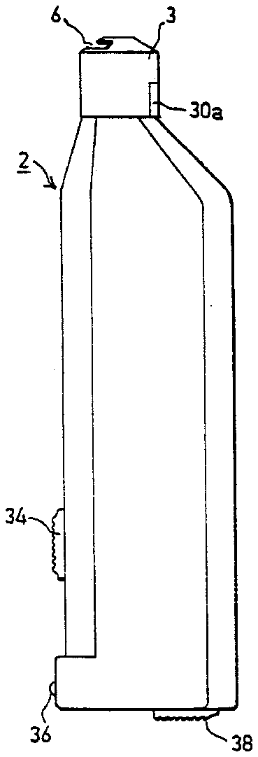
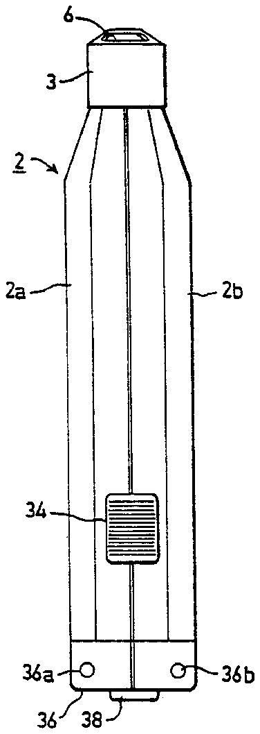
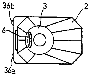
FIGS. 1, 2 and 3 are side, front and top views, respectively, of one form of cutter device constructed in accordance with the present invention;
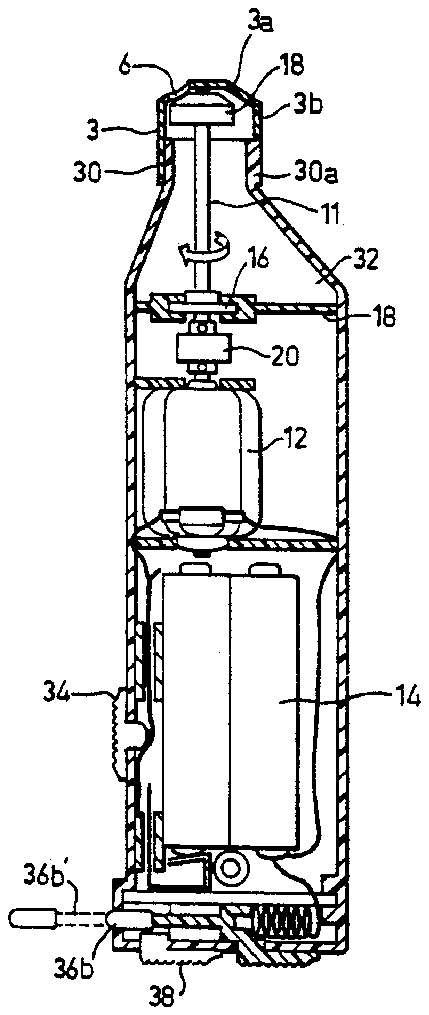
FIG. 4 is a side view of the device of FIGS. 1-3 with a part of the housing removed to show its internal structure;
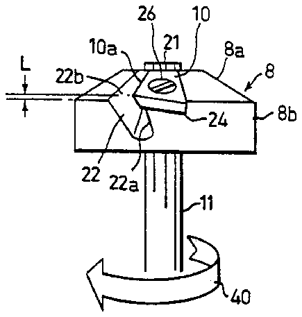
FIG. 5 is an enlarged fragmentary view illustrating the rotatable cutting head in the device of FIGS. 1-3;
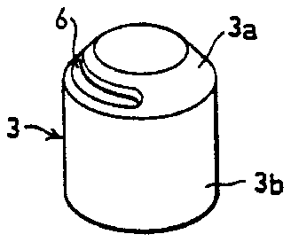
FIG. 6 is a three-dimensional view of the removable housing section covering the rotatable cutting head;
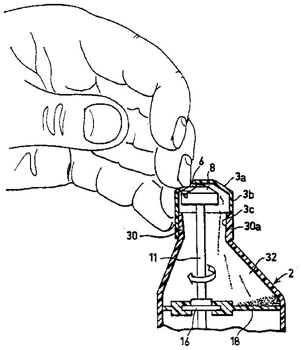
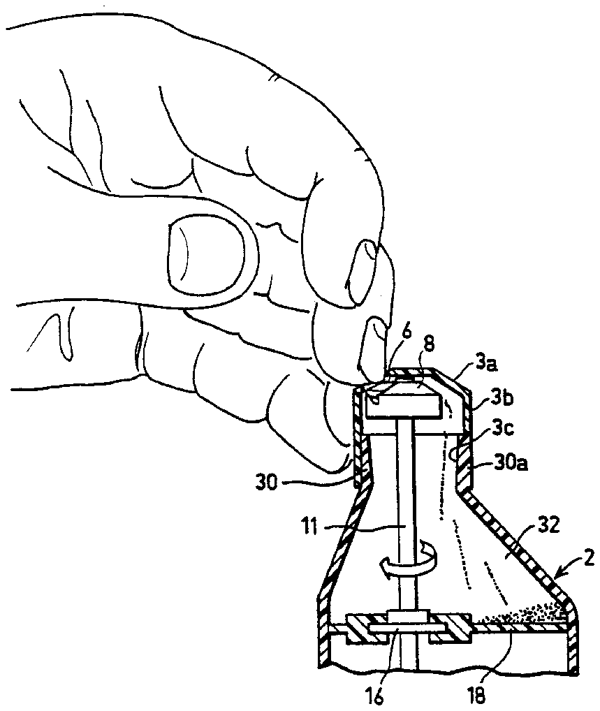
FIG. 7 illustrates the manner of using the device of FIGS. 1-3;
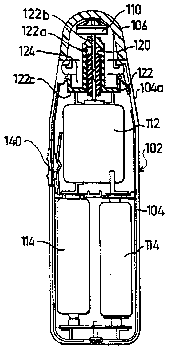
FIG. 8 is a side view, with parts shown in section, illustrating a second form of cutter device constructed in accordance with the present invention;
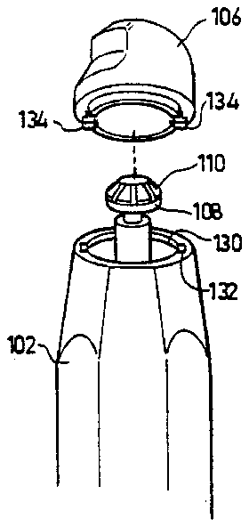
FIG. 9 is an exploded view of the end of the cutter device of FIG. 8 mounting the cutting blade;
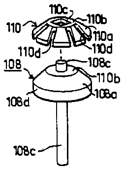
FIG. 10 is an exploded view illustrating the cutting blade of FIG. 8 and the rotatable head to which it is mounted;
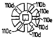
FIG. 11 is a plan view of the cutting blade of FIG. 8; and
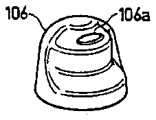
FIG. 12 is a perspective view of the housing cover at the cutting end of the device of FIG. 8.
DESCRIPTION OF PREFERRED EMBODIMENTS
The Embodiment of FIGS. 1-7
The cutter device illustrated in FIGS. 1-7 of the drawings comprises a housing, generally designated 2, constituted of two half-sections 2a, 2b and a removable end section or cover 3. The half-sections 2a, 2b are secured together by a threaded fastener 4 (FIG. 1), and the cover 3 is removably received over one end of the housing. The removable cover 3 is formed with a slot 6 at one end for receiving the nail to be cut by a cutting blade within the housing. The remainder of the housing is shaped so as to be conveniently grippable by the user for manipulating the device.
The removable cover 3 encloses a rotatably-mounted cutter head 8 carrying a blade 10 having a cutting edge 10a adapted to move under slot 6 so as to cut the nail inserted into the slot. The cutter head 8 is coupled by a shaft 11 to an electric motor 12 disposed within the housing 2 and supplied by electrical batteries 14 also disposed within the housing. Shaft 11 is supported by a bearing 16 carried by a partition 18 integrally formed in the two housing sections 2a, 2b, and is coupled to motor 12 by a coupling member 20, e.g., a gear.
The cutter head 8 is of a solid, preferably metal, construction. It is formed with a bore for receiving the motor drive shaft 11, and to which it is secured by an end fastener nut 21.
Cutter head 8 includes a frusto-conical section 8a and a cylindrical skirt section 8b, and is formed with a recess or cavity 22 extending substantially radially through both sections 8a, 8b. The cutter head is further formed with a seat 24 on which the blade 10 is secured by a threaded fastener 26.
As shown particularly in FIG. 5, blade 11 is slightly longer, in the direction of rotation of the cutter head 8, than seat 24, so that the cutting edge 10a of the blade extends past edge 22a of the recess 22, but terminates slightly short of and parallel to its other edge 22b. As further shown in FIG. 5, seat 24 is formed obliquely to the rotary axis of the cutter head 8, defined by the longitudinal axis of shaft 10, such that the cutting edge 10a of blade 10 projects slightly outwardly, by the distance indicated as "L" in FIG. 5, from the outer surface of the frusto-conical section 8a of the cutter head. This distance "L" fixes the thickness of the cuttings.
The removable cover 3 enclosing the cutter head 8 includes a similar frusto-conical section 3a and cylindrical skirt 3b. Slot 6 for receiving the nail to be cut is formed in the frusto-conical section 3a in the circumferential direction. The cylindrical skirt 3b is removably received on a cylindrical end section 30 of the two housing halves 2a, 2b. In order to angularly locate the removable housing section 3, and particularly its slot 6, with respect to the cutter head 8, the housing end section 30 is formed with an axially-extending rib 30a adapted to be received within a recess (shown as a slot) 3c formed axially in the cylindrical skirt 3b.
As shown in FIGS. 4 and 7, cutter head 8 is rotatably mounted eccentrically with respect to the removable cover 3, i.e., closer to the side of cover 3 formed with the slot 6. Thus, there is more space between the cutter head and the opposite side of the removable housing section 3. This space enables the nail cuttings, after being cut during the rotation of the cutter head, to be directed by centrifugal action to, and to accumulate within, a compartment 32 defined by the partition 18. This compartment may be emptied of the cuttings by merely removing cover 3 and pouring out the accumulated cuttings through the thus- opened end of the housing.
The illustrated cutter device further includes a manually-operated electrical switch 34, and an electrical plug 36 including a pair of prongs 36a, 36b, extensible by a slide 38 to the broken-line portion shown by prong 36b' in FIG. 4, in order to insert the plug into a socket for recharging the batteries 14, when rechargeable batteries are used.
The cutter device illustrated in FIGS. 1-7 is used in the following manner:
Whenever a fingernail or toenail is to be cut, electric motor 12 is energized by operation of switch 34 to rotate the cutter head 8. The nail to be cut is inserted into slot 6 as shown particularly in FIG. 7.
It will be seen that the cutting edge 10a extends substantially perpendicularly to the direction of elongation of slot 6, and thereby to the nail to be cut, and that cutting head 8 is rotated to drive the cutting edge 10a (in the direction shown by arrow 40 in FIG. 5) substantially parallel to the direction of the slot. Thus, the nail inserted into the slot 6 is cut neatly, quickly and safely by the cutting edge 10a of the blade 10, without any significant component of force applied outwardly with respect to the nail tending to break it.
The cuttings are automatically directed by centrifugal action, produced by the rotation of the head, away from the slot 6 and into the space between the cutting head and the cover 3 opposite to the slot, and fall by gravity to the bottom of compartment 32. Whenever desired, compartment 32 may be emptied of the cuttings by merely removing the cover 3 and inverting the housing to pour out the cuttings from the thus-opened end of the housing.
It will thus be seen that the illustrated cutter device is convenient, quick and safe to use since only the fingernail projecting through slot 6 is engageable by the cutting edge of the cutter head, and accumulates all the cuttings within it for easy removal whenever desired.
The Embodiment of FIGS. 8-12
The cutter device illustrated in FIGS. 8-12 of the drawings comprises a housing, generally designated 102, including a main section 104, and a removable cover 106 at one end. The removable cover 106 is of generally conical configuration. The main section 104a is of generally cylindrical configuration to facilitate manually gripping and manipulating the device, but its end portion 104b, receiving the removable cover 106, is of frusto-conical configuration to provide a smooth juncture with the cover.
As shown particularly in FIG. 12, the removable cutter 106 is formed with a slot 106a elongated in the circumferential direction for receiving a nail to be cut by a cutting blade within the housing. Thus, as shown particularly in FIGS. 9 and 10, the cover 106 encloses a cutter head 108 to which the cutter blade 110 is fixed. The cutter head 108 is coupled to an electric motor 112 disposed within the housing 102 and supplied by electrical batteries 114 also disposed within the housing.
The cutter head 108 is of a solid, preferably metal, construction. It includes an outer conical (or frusto-conical) surface 108a substantially conforming to the inner conical surface of cover 106. A flat surface 108b is formed centrally of conical surface 108a and includes a central cylindrical projection 108c for use in securing the cutter blade 110 to the head 108. The cutter head 108 is further formed with a cylindrical skirt section 108d and a stem 108e depending from the latter section, i.e., on the side of the cutter head opposite to that receiving the cutter blade 110.
The cutter blade 110 is formed with a conical (or frusto-conical) section 110a conforming to the conical surface 108a of the cutter head 108. Blade 110 is further formed with a flattened surface 110b engageable with flat surface 108b of the cutter head, and with a central opening 110c for receiving projection 108c of the cutter head. Opening 110c of the blade is of non-circular (e.g., square) configuration. Thus, blade 110 is fixedly secured to the head 108 by passing projection 108c through opening 110c and then splaying the projection, e.g., by an impact implement, to spread or turn out the projection and to fill the opening 110c.
Conical section 110a of the cutter blade 11 is punched out with a plurality of radially-extending slots 110d around the circumference of the blade. The radial slots 110d extend completely through the thickness of the blade, starting from its outer periphery to the flattened central region 110b, which is not slotted. The radial slots thus form a plurality of spaced radially-extending cutting edges 110e extending from the unslotted central region to the outer periphery of the blade. It will thus be seen that the cutting edges 110e of the cutting blade 110 also extend substantially radially of the conical surface 108a of head 108 and perpendicularly to the slot 106a formed in the cover 106 receiving the fingernail to be cut.
The cutter head 108 is coupled to the electric motor 112 by a flexible tubular coupling 120 (FIG. 8) receiving the cutter head stem 108e at one end, and the shaft 112a of the electric motor 112 at the opposite end. The flexible tubular coupling 120, e.g., of rubber, passes through a plastic bushing 122 mounted within the housing 102 between motor 112 an the cutter head 108. Bushing 122a is formed with a passageway 122a for receiving the flexible tubular coupling 120. Passageway 122a terminates at one end in an opening 122b of smaller diameter than the passageway for receiving the stem 108e of the cutter head. The opposite end of bushing 120 is formed with a disc section 122c closing the respective end of the housing so as to define a compartment 124 with the housing for receiving the nail cuttings.
The end of housing 102 closed by cover 106 is formed with a circumferentially-extending rib 130 and with a pair of axially-extending slots 132 on diametrically-opposite sides of the rib 130, to define, with the rib, a bayonet-type slot for receiving a pair of bayonet-type projections 134 formed in the end of the cover 106. The cover 106 may be easily attached to the housing 102 by merely passing the projections 134 of cover 106 through slots 132 in the housing, and rotating the cover; and may be as easily removed by reversing this sequence of steps.
Housing 102 carries an electrical switch 140 which may be operated to energize motor 112 and thereby to rotate head 108, and the blade 110 carried thereby.
The cutter device illustrated in FIGS. 8-12 is used in the following manner:
Whenever a fingernail or toenail is to be cut, electric motor 12 is energized by operation of switch 140 to rotate the cutter head 108 and the cutter blade 110. The nail to be cut is inserted into slot 106a. As head 108 rotates, the cutting edges 110e of the cutting blade 110 move substantially perpendicularly to the direction of elongation of the slot 106a in the cover 106, and to the nail received in the slot. Accordingly, the cutting edges 110e will neatly cut the nail received in the slot. The cuttings will accumulate within compartment 124 defined by the housing 102 and the disc section 122c of the bushing 122.
Emptying the housing of the cutting accumulated within compartment 124 may be easily done by merely rotating cover 106 to align its projections 134 with slots 132, and then removing the cover from the housing.
In the arrangement illustrated in FIG. 12, the cover may be rotated 180° to selectively position the slot on one side of the housing for use by right-hand persons, or on the opposite side for use by left-hand persons.
While the invention has been described with respect to two preferred embodiments, it will be appreciated that many other variations, modifications and applications of the invention may be made.


