- 5v
Description
- (No Model.)
H'.- LA GASSE. FINGER NAIL TRIAMMBR.
No.' 52.3;70'8. Patented July 31, 1894.
WITNESS-Es; n
UNITED STATESv PATENT OFFICE.
HENRY LA oAssE, 0E ROCHESTER, NEWv YORK.
FINGER-NAIL TRIMMER.
SPECIFICATION forming part of Letters Patent N o. 523,708, dated July 31, 1894.
Application led October 17, 1892. Serial No. 449,142. (No model.)
To @ZZ whom it may concern.-
Be it known that I, HENRY'LA CASSE, of Rochester,inthe countyofMonroe,in the State of New York, have invented new and useful Improvements in Finger-Nail Trimmers, of which the following, taken in connection with the accompanying drawings, is a full, clear, and exact description.
My invention relates to improvements in finger nail, trimmers, and has for'its object the production of la simple and practical device, which is economically manufactured, easily operated, and is durable and efficient in use; and to this end it consists in the detail construction and arrangement of the parts, al1 as hereinafter more particularly described and pointed out in the claims.
In describing this invention, reference is had tothe accompanying drawings, forming a part of this specification, in which like letters indicate corresponding parts in all the views.
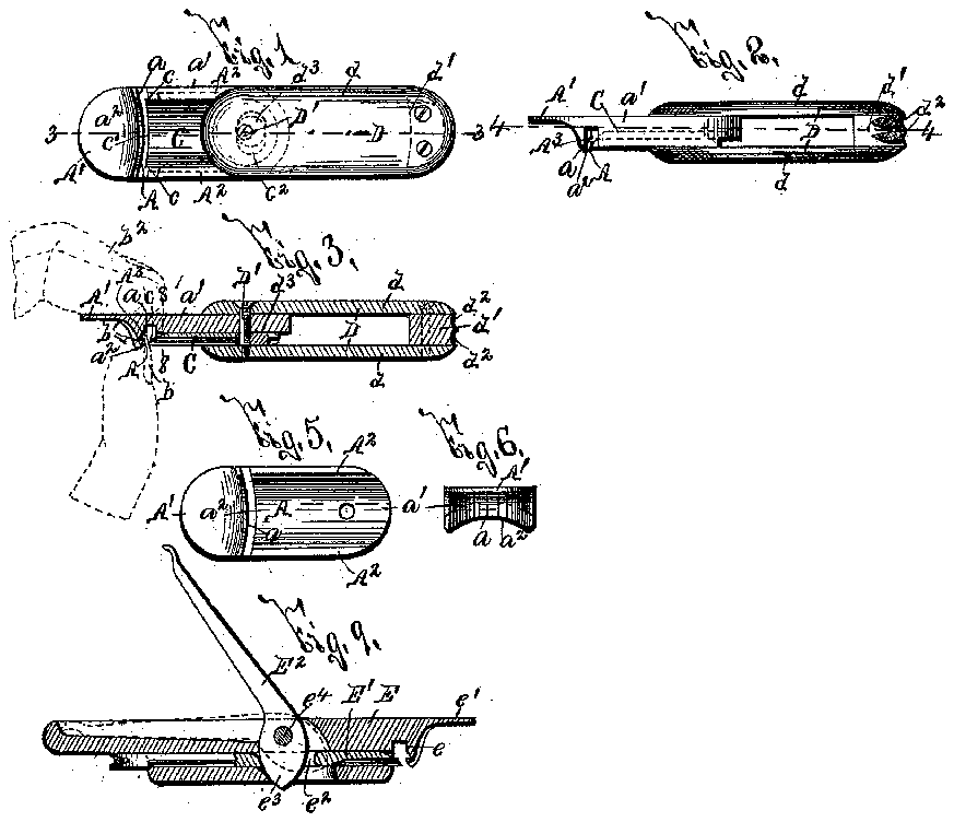
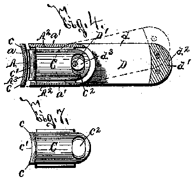
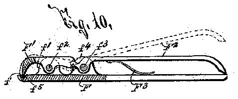
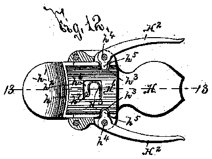
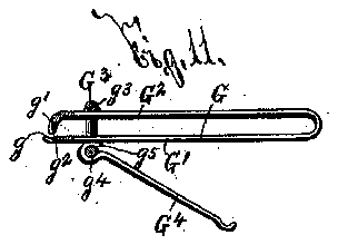
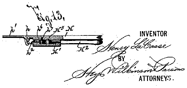
Figures 1 and 2 are respectively inverted plan and side elevation of my improved finger nail trimmer. Fig. 3 is a longitudinal Vertical sectional view, taken on line -3-3, Fig. 1, portions of a users thumb and rst linger being shown by dotted lines. Fig. 4 is a horizontal sectional view, taken on line -4-4-, Fig 2. Figs. 5 and` 6 are respectively inverted plan view and front edge view of the detached bar o r plate provided with the finger nail supporting face. Fig. 7 is an inverted plan view of the detached knife movable toward and away from said face. Fig. 8 is a transverse vertical sectional view, taken on line -8- 8, Fig. 3. Fig. 9 is a lon gitudinal sectional view of a modiied form of my invention. Fig. 10 is an elevation,vpartly in section, of an additional modified form ofv my improved finger nail trimmer. Figs.` 1l and l2 are respectively elevation, partly in section, andlongitudinal horizontal sectionaly views of stillfurther modified forms of my invention, and Fig. 13 is a longitudinal vertical sectional view, taken on line -13-13-, Fig. 12.
When fingernails are trimmed either by a file, scissors, ora knife, and the form or curve of the outer edge of the nail is governed solely by the operators eye, it is extremely diicult to similarly trim or cut the outer edges of different finger nails in substantially the samer curves, although it is extremely desirable to trim them with uniformity in order that thel hand may present a neat and 'pleasing appearance.
By my present invention I supporty the fingernail, while being trimmed, by a face formed convex in cross section and provided with a concave lower edge, and then clip off the outer edge ,of the finger nail by a knife formed with an edge havingits ends arranged in advance of the' plane of its central portion and beneath the plane of said central-portion. The outer edges of the finger nails are thus cut with a knife having the required curvature, and consequently present a uniform and neat appearance.
In the preferred example of Y my invention illustrated at Figs. 1 to 8 inclusive, the finger nail supporting face `A- is formed upon an ear projecting outwardly from the lower The fa'ceflA-l', as best seen at Figs. 1, 4, and 5 is formed convex in cross section, and is provided with a concave lower edge 0,2- as seen in Fig. 6.
-A- is an engaging projection upon the bar -ct which extends outwardly beyond the ear -a-. l
In the operation of my-improved trimmer, as indicated by dotted lines at Fig. 3, the operator forces the lower edge of the ear -cL- between his nger nail"-b-, to be trimmed, and the adjacent portion of the finger -b-, and places his thumb -bzupon the upper face of the projection -A-.
It will be readily understood that the described construction of the ear -ctand projection -A- permits the outer edge of the nail to be trimmed, to lie firmly against the lower portion of the nail supporting face '-y-A-, and enables the user to readily support my improved linger nail trimmer byhs thumb --b2- and his linger -b carrying the nail to be trimmed. l
-C-is the knife for trimming offthe outer edge of the linger nail -b-. As clearly seen at Figs. 2, 3, 4, 7, and 8, the edge of said knife is inclined upwardly, and is formed with its extremities or corners -c-carranged ,in advance of the cand disposed beneath the plane of'said central portion. The cutting edge of "the knife -C-- is, therefore, of the desired curvaplane of its central portion roo ture to conform to the transverse curvature` of the nger nail, and to bring the outer edge of the finger nail to the desired curvature when the same is clipped by said knife. The knife -C- is movable toward and away from the face A in order to clip the finger nail, and to facilitate its ready movement, the side edges of the knife are movable in guides A2- formed in the under face of the bar a at the inner side of the ear --cL-. When the knife is in its normal position there is ample space between its cutting edge and theface A- to permit the ready insertion of theedge of the finger nail, and, in order to facilitate the cutting of the finger nail by the knife, the face A is formed with a curved groove -A3- having its central portion elevated above its extremities. This face -A- is also frequently formed of metal much softer than the knife edge, so that, even when continually used, the knife edgeV is uninjured by said face, and remains sufficiently sharp for a long time.
It is evident that the curve of the face -A and the contour of the lower edge of said face and of the cutting edge of the knife may be suitably t varied to vconform to the desired form of the nail, and that, instead of making the knife C of sufficient size to trim the entire outer edge of the nail, it may be much smaller and may be capable of trimming only a portion of the edge of the nail at a time.
The knife is reciprocated toward and away from the face -A- by means of a lever -D-, which also forms a suitable case for the bar -aand the knife C--. This case preferably consists of a pair of separated plates -d--dhaving a block d-- interposed between their outer ends. The outer face of the block cZ- is formed with roughened faces d2-q which act as files to smooth off the edge of the finger nail afterit is trimmed.
The inner ends of the plates -d--cZ- are secured to the'bar -a-- by a pivotal pin -D upon which is xed an eccentric d3 movable in a laterally elongated slot c2- formed near the inner end of the knife C-.
As previously described the user supports my improved finger nail trimmer by his thumb and the finger, the nail of which is to be trimmed, and, as with the other hand he moves the outer end of the lever -D upon its pivot D- to either side of its position, shown at Figs. l, 2, 3, and 4, the knife C is forced outwardly until its cutting edge clips off the edge of the finger nail held against the face -A-. This movement of the knife is produced by the fact that the eccentric cl3-f is so mounted on the pivotal pin D' that when the knife and handle are in alignment as seen in full lines in Fig. 4, the knife is retracted; but as the handle is moved to either side of this position as seen in dotted lines, the eccentric turns in the slot 'c2 and causes the knife to move forward to do the cutting.
and knife eC- are forced between the plates -d-dof the lever -D, and the finger nail cleaner may be then readily carried in the pocket or laid aside without liability of injury to one coming in contact therewith. v
At Fig. 9 I have shown a modified form of my invention in which the frame -E- is provided with a finger nail supporting face e and an engaging projection -ecorresponding to the like parts -A-A- of the bar -a' illustrated at Figs. 1 to 6 inclusive. The knife -E- of this form of my inventionis provided at its rear end with a slot @2- for receiving the short arm e3- of a lever -EL-.pivoted at -e4 in a plane at right angles to the longitudinal plane of the knife -E. As this lever is `rocked downwardly or upwardly the knife -E is forced toward or away from the face e.
At Fig. 10 a form of my invention is shown in which the finger nail supporting facef is formed at one end of a frame F provided with upturned ears f to which at -f2 is pivoted a knife -F having its edge movable toward the face f-.
elevate the lever -F2- and normally separate the edge f5 of the knife -F- from the face -f. As the outer end of the lever F2 is forced toward the `corresponding end of the frame -F, the edge -f5- of the knife -F clips off the edge of the tinger nail supported upon the face -f-.
My improved finger nail trimmer, shown at Fig. ll, consists of a spring bar G having one arm -G- formed with a nail supporting face -g and the other arm -G2- with a downturned ear ghaving a suitable cutting edge -g2- movable toward and away from the face -g-. G3- is a link having its top bar -g3- suitably supported above the upper face of the top bar -G2 of the frame -G, and having its lower bar g4- slightly separated from the under face of the arm -G A lever G4 is hinged upon the arm g4 of the link -G3, and is formed `with a projecting end -g5, which acts as a cam to force the free end of the arm -Gragainst the edge g2 as the free end of the lever -G4- is forced against the adjacent face of the frame arm -G'.
At Figs. l2 and 13 I have shown a construction of my improved finger nail trimmer, in which the frame II is formed with a finger nail supporting face h and an engaging projection -h of similar construction to the like parts -A--A- of the bar af-d shown at Figs. 1, 2, 3, 4, 5, and
The knife -I-I- is guided in the frame H, and is formed at one end witha cutting edge -hL- movable toward andaway from the face -h, and is formed with grooves or sockets 7t3 extending inwardly IOO IIO
is withdrawn to its position shown at Figs.
l2 and 13, and this action is facilitated by a spring -HS- mounted in the slot -h6 in the knife -H- and arranged with one end secured to a pin k7- projecting from the under face of the top bar of the frame -H- into said slot and with its other end bearing against the rear side `of said slot.
The operation of my invention will be readily perceived from the foregoing description and upon reference to the drawings, and it will be particularly noted that its parts are simplein construction, are economically manufactured, readily assembled, and -are durable and effective in use, and serve to trim the nails uniformly, and thus add greatly to the appearance of thev hand. It will be understood, however, that the detail construction and arrangement of the parts of my finger nail trimmer may be considerably varied without departing from the spirit of my invention. v
Having thus fully described my invention, what I claim as new, and desire to secure .by Letters Patent, is-
1. In a linger nail trimmer, the combination with a bar having a laterally projecting ear said ear provided at its inner vside with a nger nail supporting face, and an engaging projection extending in line with the body of the bar beyond said ear; of a knife, and means for moving its cutting edge into contact with said face, substantially as and for the purpose specied.
2. -In a finger nail trimmer, the combination of a bar having a lengthwise guide and a lat-l erally extending nger nail supporting face, and a knife movable lengthwise of thebar in said guide toward and away from said face, and formed with an edge having its ends arranged beneath the plane of the central portion thereof, substantially as and for the purpose specified.
3. In a finger nail trimmer, the combination with a bar having alengthwise guide and provided with a laterally extending finger nail supporting face, and a knife having its side edges moving in said guide and its cutting edge movable into and out of contact with said face, the body of the knife having a laterally elongated slot ear near its inner end; of a lever comprising two separated plates connected at their outer ends so as to form a hollow handle of a size to receive said bar and knife, a pivotal pin through the inner ends of the plates and bar and passing through said slot in the.knife, and an eccentric standing within said slot and so fixed on the pivotal pin that when the bar is opened andin alignment with the handle the knife is completely retracted, substantially as and for the purpose specified.
4. The combination with a bar provided with a linger nailsupporting face, and a knife movable alongside the bar toward and away from said face and having a lateral slot near its rear end; of a lever pivoted to the bar and formed of two separated plates connected at their outer ends for receiving said bar and knife, and an eccentric fixed on the pivotal pin of thelever and standing within said slot for operating said knife, substantially as and for the purpose specified. v
5. The combination with a bar having a lengthwise guide and provided with a laterally extending linger nail supporting face formed convex in cross section and with a lengthwise engaging projection at one side of said face and extending beyond the same, a knife having its edges mountedin said guide and vhaving a concave cutting edge movable toward and away from said face,and a lever connected, substantially as described, to said knife for reciprocating the same in said guide, substantially as and for the purpose set forth.
6. The combination with a bar having a lengthwise guide and provided with a laterally extending linger nail supporting facev formed convex in cross section said bar also having a lengthwise engaging projectionat one side of said face and extending beyond the same, a knife having its edges mounted in said guide and having a concave cutting edge movable toward and away from said face, a lever pivoted to said bar, and an eccentric on the pivotal pin and engaging said knife for reciprocating the same in said guide, substantially as and for the purpose set forth.
In testimony whereof I have hereunto signed my name, in the presence of two attesting witnesses, at Rochester, in the county of Monroe, in the State of New York, this 5th day of October, 1892.
- HENRY LA CASSE. Witnesses:
HAMPDEN HYDE, ETTA WEISBURG.
IOC
