- 1central strip
- 5upper end
- 20member
- 21member
- 22cutters or cutting-jaws
- 24slot
- 25slot
- 26transverse groove
- 27pivot-pin
- 28connecting-piece
- 29slot
- 30groove
- 32loose disk
- 33housing
- 34overhanging boss or projection
- 35central opening
- 36rivet
Description
No. 67l,793.' Patented Apr. 9, 90!.
' J. C. ERNST.
FINGER NAIL CLIPPER. (Application flied FSb. 12, 1901:,
(No Model.)
WITNESSES. NVENTOR.
yaw. (SW6 6 THE qoams men: co, mofauma. wAmma-rou. o. c.
UNITED STATES PATENT ()EEICE.
JOHN C. ERNST, OF ANSONIA, CONNECTICUT, ASSIGNOR OF ONE-HALF TO RUDOLPH N. J OHNQUEST, OF SAME PLACE.
FINGER-NAIL CLIPPER.
SPECIFICATION forming part of Letters Patent No. 671,793, dated April 9, 1901.
Ap lication fil d February 12, 1901. Serial No. 46,971. (No model.)
To all whont it may concern.-
Be it known that I, JOHN C. ERNST, a citizen of the United States, residing at Ansonia, county of New Haven, State of Connecticut, have invented certain new and useful Improvements in Finger-Nail Clippers, of which the following is a specification.
My invention relates to the class of fingernail clippers in which curved cuttingjaws normally separated by spring action are moved toward each other, as in the act of clippinga nail, by an operating-lever; and my invention has for its objects to simplify and cheapen the construction, so that the cost of production can be appreciably reduced, to greatly improve their operation in use, to provide a simple and convenient locking device that will retain the cutting-jaws in the closed position and the operating-lever wholly out of the way, and, furthermore, to render the device less bulky and cumbersome and more attractive in general appearance than any device of the character that has heretofore been placed upon the market.
With these ends in view I have devised the simple and novel nail-clipper of which the following description, in connection with the accompanying drawings, is a specification, reference characters being used to designate the several parts.
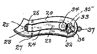
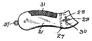
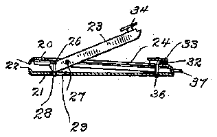
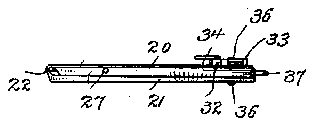
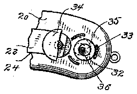
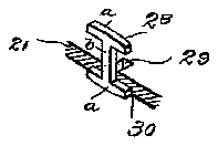
Figure l is a plan view of my novel nailclipper in the closed position; Fig. 2, an inverted plan view; Fig. 3, an edge view, also in the closed position; Fig. 4, a longitudinal section in the open position, these views all being natural size; Fig. 5, adetail view, partly in horizontal section, on an enlarged scale, illustrating the means for locking the operating-lever in its closed or out-of-the-way position, as in Figs. 1 and 3; and Fig. 6 is a detail perspective showing the operating-lever and the connecting-piece detached, the lower member being in horizontal section.
The body of my novel clipper consists of two members 20 and 21, which for convenience I will term the upper and lower members, respectively. This body may be made from one piece of spring metal or of two pieces rigidly secured together, as may be preferred, and either member or both mem- 5o bers may be spring members. Ordinarily, however, member 20 will be made relatively rigid and member 21 sufficiently resilient to throw the cutters or cutting-jaws 22, carried by the free ends of the members, to the open position.
23 denotes the operating-1e ver, which is pivoted in a slot 24 in the upper member. The slot and the operating-lever are so shaped relatively to each other that in the closed position the operating-lever will lie wholly in the slot and flush with the top surface of the upper member. The operating-lever is provided in its forward end with a vertical longitudinal slot 25 and in its upper side with a transverse groove 26, which intersects the rear end of the slot, as clearly shown in Fig. 6. The operating-lever is secured in place by means of a pivot-pin 27, which is shown as passing transversely through the operating-lever and transversely through the upper member on opposite sides of slot 25. The operating-lever is connected to the lower member by means of a detachable connecting-piece 28. This connecting-piece is in shape a double T-that is to 7 5 say, two parallelend pieces aare connected by a central strip 1), lying at right angles to the end pieces. Near the forward end of member 21 is a longitudinal slot 29, and lying transversely to the mid-length of this slot on the outer side of the member is a groove 30, which is adapted to just receive one of the end pieces a of connecting-piece 28, as clearly shown.
In assembling connecting-piece 28 is passed upward through slot 29, and when the upper cross-piece a has passed through said slot the connecting-piece is given a quarter-turn and the lower end piece a. is caused to lie in the transverse groove 30. The operating-lever may then be engaged with the upper arm of 0 the connecting-piece, the operating-lever being inserted in approximately the position shown in Fig. 4:, the central strip b of connecting-piece 28 passing into vertical slot 25 in the operating-lever and the upper end 5 piece a, engaging transverse groove 26 in the operating-lever, as will be understood from Fig. 4 in connection with Fig. 6. It will be noted from Fig. 4: that the resistance-arm of the operating-lever is relatively short and that in use power is applied directly to raise the lower member to the closed position, so that there is no loss of power.
31 denotes a file, which I preferably pro vide on the outer side of member 21.
As a means for retaining the operating-lever in the closing position I provide a loose disk 32 in a housing 33, which is adapted to engage the lower end of the operating-lever by gravity only. I have shown the lower end of the operating-lever as provided with an overhanging boss or projection 34, which also serves as a finger-piece. The locking-disk is provided-with a central opening 35, and the housing is retained in position by a'central rivet 36, which passes through the opening in the disk, as is clearly shown in Fig. 5, in which the top of the housing and a portion of the overhanging boss are removed, rivet 36 being in section. In this figure the locking-disk is shown in full lines in the unlocking position and in dotted lines in the looking position. The operation of locking and unlocking the operating-lever is by gravity alone. The operator simply presses the opcrating-lever down into slot 24, and if he desires to lock it there holds the implement with the housing end upward. As soon as the implement is placed in this position the locking-disk will drop by gravity to the relative position indicated by dotted lines in Fig. 5, which will place the edge of the lockingdisk under the edge of the overhanging boss, so that the instant the operator relieves the pressure upon the operating-lever the resiliency of the lower member or of both members, as may be, which Will be exerted to move the jaws toward the open position, will lock the lever in the closed position through frictional contact of the locking-disk with the housing and the overhanging boss. The parts will remain securely locked in this posit-ion most unlimited extent without disengagement of the operating-lever. To disengage the operating-lever is equally simple.
lieves the spring-pressure of the operatinglever upon the locking-disk, so that the latter will drop downward in the housing to the and release the operating-lever.
similar use.
claim-- member having a pivoted operating-lever with The operator merely holds the implement with. the housing end downward and presses in-' ward upon the overhanging boss. This re a slot at its forward end which receives the central piece of the connecting-strip and a groove which receives the end piece.
2. A finger-nail clipper comprising members provided with cutting-jaws, one of said members having a connecting-piece with a central strip and an end piece and the other member having a pivoted operating-lever engaging the connecting-piece, the free end of said operating-lever having an overhanging boss, and a gravity-disk upon the member adapted to lock the operating-lever in the closing position.
3. In an implement of the character described the combination with a member 21 having a vertical longitudinal slot near one end thereof and a groove in its outer side transverse to the slot and a member 20, of a connecting-piece consisting of two end pieces and a central strip, said parts being assembled by passing one end piece through the slot, then giving the connecting-piece a quarter-turn and placing the other end piece in the groove, and a pivoted operating-lever carried by member 20 and having at its forward end a slot to receive the central strip and a groove to receive the end piece.
4:. In an implement of the character described the combination with members having cutting-jaws which normally remain apart, of an operating-lever pivoted to one member and engaging the other member, whereby said members may be moved to the closed position, said operating-lever having an overhanging boss, and a gravity locking-disk upon the member to which the lever is pivoted which is adapted to engage the boss to lock the lever in the closing position.
5. In an implement of the character described the combination with members having cutting-jaws which normally remain apart, one of said members having-a housing, of an operating-lever provided with an overhanging boss and pivoted to one member and enand the implement may be handled to an algaging the other member, and a loose disk within the housing which is adapted when the lever is pressed inward to lock or release said lever by gravity.
6. In an implement of the character described the combination with members having cutting-jaws which normally remain apart, of an operatinglever provided with an overhanging boss and pivoted to one member and engaging the other member, a housing upon relative position shown in full lines in Fig. 5" The implement may or may not be provided with a ring? 37 for attachment to a watch-chain or any the member to which the lever is pivoted, a central rivet by which the housing is secured in place and a locking-disk within the housing having a central opening through which the rivet passes loosely, said disk being adapt- Having thus described my invention, I
ed to engage the overhanging boss by gravity.
7. A finger-nail clipper comprising members provided with cutting-jaws which normally remain apart, one of said members having a connecting-piece with a central strip and an end piece and the other member having a pivoted operating-lever with a slot at its forward end to receive the central piece and a groove which receives the end piece and means for locking the operating-lever in the closing position.
8. A finger-nail clipper comprising members provided with cutting-jaws which normally remain apart, an operating-lever pivoted to one member and engaging the other member and a gravity-disk carried by the member to which the lever is pivoted and [0 which is adapted to lock the lever at either the open or closing position.
In testimony whereof I afii'x my signature in presence of two witnesses.
JOHN C. ERNST. Witnesses:
REUBEN H. TUCKER, RUDOLPH N. J OHNQUEST.