- 5line
Description
No. 691,!26. Patented Ian. I4, l9lD2.
E. FDRQUIGNON.
NAIL CUTTER AND FILE.
(Application filed May 15. 1901.)
(No Model.)
liiimu umnmmmlm WITNESSES A Tram/Us win 'ra'rns a'rnnir t EMIL FORQUIGNON, OF NEW] YORK, N. Y.
NAEL CUTTER AND FlLE.
To all whom it nutty concern.-
Be it known that I, EMIL FORQUIGNON, a citizen of the United States, and a resident of the city of New York, borough of Manhattan, in thecounty and State of New York, have invented certain new and useful Improvements in Nail Cutters and Files, of which the follo\ving is a full, clear, and exact description.
The object of the invention is to provide a new and improved tool for use as a nail cutter and file arranged to permit of conveniently and accurately cutting finger and toe nails and filing the same, the tool being simple and durable in construction and adapted to fold into a comparatively small space for pocket use or as a charm for a watch-chain.
The invention consists of novel features and parts and combinations of the same, as will be fully described hereinafter and then pointed out in the claims.
A practical embodiment of the invention is represented in the accompanying drawings, forming a part of this specification, in which similar characters of reference indicate corresponding parts in all the views.
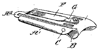
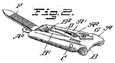
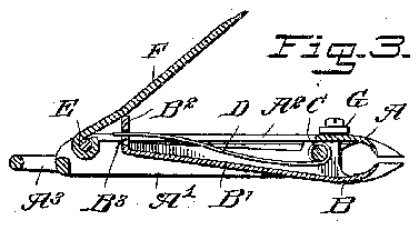
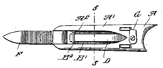
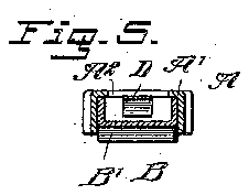
Figure 1 is a perspective View of the improvement in a folded position. Fig. 2 is a like view of the same in an open position. Fig. 3 is a longitudinal sectional elevation of the same. Fig. 4 is a plan View of the same, and Fig. 5 is a transverse section of the same on the line 5 5 in Fig. 4.
The improved nail cutter and file consists, essentially, of cutters A and B, connected with each other by a pivot O and having their cutting edges reversely curved to the shape of the nail tobe out, as is plainly illustrated in the drawings, one side of the cutters being extended to reach and perfectly cut the nails at the side corners thereof. The backs of the cutters A and B are curved rearward from the cutting edges and in opposite directions-that is, the back of the cutter A is curved-upward and rearward and that of the cutter B is curved downward and rearward. The tails A and B of the cutters A and B are made Lil-shaped in cross-section, as is plainly indicated in Fig. 5, the tail B fitting into the tail A, so that the latterforms a casing for the tail B and incloses and conceals the said tails when the several parts are closed. A spring D is held on the pivot C of Letters latent No. 691,126, dated January 14,1902.
Serial No. 60,354. (No model.)
and engages with its free end an aperture B in a lug B extending upwardly from the rear end of the tail B, said spring serving to normally hold the cutters in an open position, as indicated in Figs. 2 and 3. The upper end of the lug B is adapted to be engaged by one face of a file F, hung on a pivot E, carried in the rear or outer end of the tail A, so that when said file F is swung forward down to the cutter A it presses on the lug B and imparts a swinging motion to the tail B and the cutter B, so as to move the cutting edge of the cutter B toward the cutting edge of the cutter A and finally close the cutters one upon the other, and thereby out the nail inserted between the two cutters while the same are in an open position. \Vhen the pressure is released on the file F, then the spring D again opens the cutters A and B and returns the file F to the position shown in Fig. 3.
The top of the tailA is formed with a cutout portion or slot A corresponding to the shape of the file F, so as to receive the same when the latter is swung into a completelyclosed position, as shown in Fig. 1, and when the file is in this position it can be locked therein by a catch G, pivoted on the top of the cutter A and adapted to engage the free end of the file F. The rear end of the tail A is formed with a loop or eye A for attaching the device to a chain, ring, or like article, said loop also serving to form a rest for the file F when the same is extended, as shown in Figs. 2 and 4, to permit of using the file for filing the nails or cleaning the same. It is understood that in this latter case the tailA forms a handle for the file F, so as to allow of conveniently manipulating the file for its legitimate purpose.
From the foregoing it is understood that by manipulating the file F in the manner described the cutters A and B are closed so that their cutting edges accurately cut the fingernail inserted between the cutting edges. By having the cutting edges in the reverse shape of the finger-nails to be cut it is evident that a proper shape is given tothe finger-nail on cutting the same, and by having the cutters extended to one side the operator is enabled to reach the corners of the finger-nails and properly trim the same close to the root. By
swinging the file F into a closed position and looking it in place in the slot A by the use of the catch G the entire device is folded into a comparatively small space for convenient pocket use.
Having thus fully described my invention, 1 claim as new and desire to secure by Letters Patent- 1. Anailcutter and file havinga pair of cutters curved reversely to the curved edge of the nail to be cut, the cutters being pivotally connected with each other, and a file hinged on. one of the cutters and adapted to engage the other cutter to close the same, as set forth.
2. Anail cutter and file havinga pair of cutters curved reversely to the curved edge of the nail to be out, the cutters being pivotally connected with each other, and a file hinged on one of the cutters and adapted to engage the other cutter to close the same, the file being adapted to fold into a slot in the cutter on which it is hinged, as set forth.
3. A nail cutter and file having a pairof cutters curved reversely to the curved edge of the nail to be cut, the cutters being pivotally connected with each other, a file hinged on one of the cutters and adapted to engage the other cutter to close the same, and a spring for a holding the cutters and the file normally open,
as set forth.
4. Anail cutterand file havinga pair of cutters curved reversely to the curved edge of the nail to be cut, the cutters being pivotally connected with each other, a file hinged on one of the cutters and adapted to engage the other cutter to close the same, the file being adapted to fold into a slot in the cutter on which it is hinged, and a catch for engaging the file and locking the same in place in the slot, to hold the cutters in a closed position, as set forth.
5. A nail cutter and file having pivoted cutters, and a file pivoted on one of the cutters and arranged to engage the other cutter and close the cutters, as set forth.
6. A nail cutter and file having a pair of spring-pressed cutters, and a file pivoted on one of the cutters and adapted to engage a lug on the tail of the other cutter, to move the latter into a closed position, as set forth.
7. A nail cutter and file having a pair of cutters pivotally connected with each other, one of the cutters having its tail end formed into a casing to receive and inclose the tail end of the other cutter, and a file pivoted on said casing and adapted to engage a lug on the tail of the other cutter, as set forth.
8. A nail cutter and file havingapair of cutters pivotally connected with each other, one of the cutters having its tail end formed into a casing to receive and inclose the tail end of the other cutter, a file pivoted on said casing and adapted to engage a lug on the tail of the other cutter, and a catch pivoted on the casing, for engaging the free end of the file and locking the latter and the cutters in a closed position.
In testimony whereof I have signed my name to this specification in the presence of two subscribing witnesses.
EMIL FORQUIGNON.
\Vitnesses:
EMMA O. KocH, THOS. W. FoLsoM.