- 1end
- 2about lines
- 13blades
- 71head
Description
Patented Mar. ll, I902.
W. S. REED.
MANIGURE KNIFE.
(Application filed Nov. 1, 1901.)
(No Model.)
. INVENTOI? 7727227 65 5.156605.
96' @913 I WITNESSES:
Am [9i A TTORNEYS rug Noams PEYEIIS ce FHOTIOLVTHO. WASHINGTON. u. c,
To (0Z7, whom it may concern:
NlTF rates Parent MANlCURE-KNIFE.
SPECIFICATION forming part of Letters Patent N0. 695,342, dated March 11, 1902.
Application filed November 1,1901. Serial No. 80,815. (No model.)
Be it known that I, I/VILLARD SALISBURY REED,'a citizen of the United States, residing at Smyrna, in the county of Kent and State of Delaware, have made certain new and useful Improvements in lVIanicure-Knives, of which the following is a specification.
Myinvention is an improved manicure implement designed for use in cutting, trimming, filing, scraping, cleaning, and otherwise caring for the nails of the fingers and toes; and the invention consists in certain novel constructions, as will be hereinafter described and claimed.
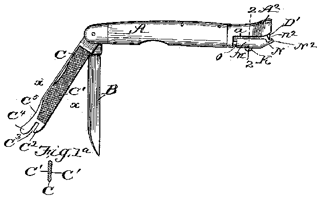
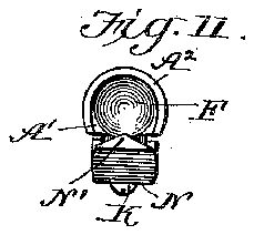
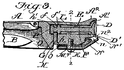
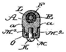
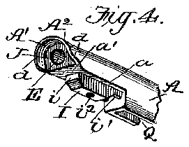
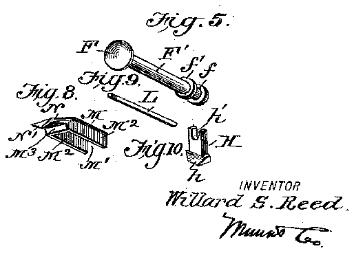
In the drawings, Figure 1 is a side view of my implement with the tile and ordinary blade open. Fig. 1 is a detail cross-section on about line a; m of Fig. 1. Fig. 2 is a crosssectional view on about lines 2 2 of Figs. 1 and 3. Fig. 3 is a partial longitudinal section of the implement. Fig. 4 is a detail perspective view of one end of the handle. Fig. 5 is a detail perspective view of the rotary cutter and its shaft. Fig. 6 is a detail perspective View of the liners. Fig. 7 is a detail perspective View of the screw for securing the cutter-bar. Fig. 8 is a detail perspective view of the cutter-bar. Fig. 9 is a detail perspective View of one of the antifriction-rollers. Fig. 10 is a detail perspective View of the locking-key. Fig. 11 is adetail elevation of the butt-end of the implement on an enlarged scale.
The handle A is provided at one end with the blades B and O and is constructed at its other end to support the rotary cutter and the parts which cooperate therewith, as will be more fully described hereinafter. The blade B is an ordinary knife-blade and, like the blade 0, may be secured in the handle A.
and springactuated in the ordinary manner. The blade 0 is of a special construction, having file-surfaces O on its opposite sides and provided at its outer extremity with a portion 0 which operates as a nail-cleaner and is separated by a slot 0 from a portion 0, which is formed as a lifter for lifting up or pressing back the flesh and skin at the root of the nail, as is desired in the lnanicuring operation. The outer edge of the blade 0 at C is curved in a concave line and sharpened or brought to an edge to adapt it for use in B and 0 formed to support the rotary cutter which is used for trimming the nails. To this end I form such handle with a recess D in its extremity, from which extends longitudinally inward a bore or opening E, which receives the shaft F of the cutter F. The recess D is open at its lower edge at D, and the bore E is intersected slightly in advance of its rear end by a channel G, in which is inserted the key II for the purpose of locking the cuttershaft F in place, as shown in Fig. 8. The outer surface of the handle surrounding the cutter F is rounded from side to side, as shown at A in Fig. 4, and slopes gradually upward toward its outer end, as shown at A in Figs. 1 and 3, thus forming a guard for the cutter F and the abutment for the forefinger of the hand holding the knife in operating upon the nails. On its inner side the handle is provided with a projecting portion I, which lies between the lateral shoulders a on the handle A and is spaced at its end 1' back from the outer end of the hub portion .I, providing a shoulder a. The inner end of the lug or projection I is adapted at t" to form a seat for the head 71 of the locking-key H, and the threaded opening is provided at i for the screw K, which secures the cutter-bar to its place, as shown in Figs. 2 and 3. The cutter has its shaft provided near its inner end with a groove f, which is entered by the bifurcated end h of the locking-key H and is provided with the outwardly-facing shoulder f adjacent to the groove f, which shoulder f forms in connection with the rotary cutter F an annular groove in which is seated the antifriction-rollers L. (SeeFigs. 2 and 3.) In practice the portions of the shaft lying on opposite sides of the groove f are made smaller than the bore E in the end of the handle, so there will be no friction between the said shaft and the handle; but the shaft will be borne entirely by the antifriction-rollers, as will be understood from Figs. 2 and The cutter-bar M is of a special construction, having the hollow or mortise M, which fits over the lug or projection I, and has the side flanges M which lap on opposite sides of said projection or lug I, and the end flange M which stands in operation in frontof the outer end of the said lug I. This cutter-bar has the opening M for the screw K, which opening is elongated longitudinally, so the cutter-bar can be adjusted in such direction to take up wear in the use of the device, as will be presently described. At its rear end the cutter-bar overlies the key H and locks the same in position, as shown in Fig. 3, and at the outer end of the said cutter-bar there is formed the neck N, which supports the point N, whose sides slope gradually, as shown in Fig. 8, and thus aid in guiding the nail into contact with the rotary cutter. It will also be noticed that the outer extremity of the cutter-bar at N is square to prevent the implement from cutting into the quick, such end N forming a stop to limit the movement of the rotary cutter toward the flesh. The neck N, as will be understood from Figs. 1 and 8, provides a throat which opens at the opposite sides of theimplement (seenin Fig. 3) and forms an outlet for the cut portion of the nail.
WVithin the recessed portion of the cutter-bar M and between the cutter-bar and the lug I, I arrange a suitable number of thin plates or liners O, which operate as washers to space the cutter bar away from the cutter and which can be removed from time to time as the parts wear to take up wear and insure the proper adjustment of the cutter-bar to the cutter at all times.
In adjusting the parts to position for use-it will be understood that the rotary cutter D has its shaft, with the rollers L applied, inserted in the bore E until the cutter F lies within the recess D, as shown in Fig. 3, and projects at its inner edge beyond the side walls d of such recess, which slope rearwardly, as
shown in Figs. 3 and 4:. The groove f will then lie opposite the channel G, and the key II will then be inserted to the position shown in Fig. 3, in which it will fit within the groove f and operate to prevent an ylengthwise movement of the cutter F and its shaft. Said cutter will then be held within the handle and will be supported so itcan turn within the antifriction rollers, thus relieving friction and rendering the rotation of the cutter very easy. The cutter-bar will then be applied, as shown in Figs. 2 and 3, and held by the screw K with the liners O in place, which liners can be removed from time to time as desired. When so applied, the cutter-bar will overlie the key H at its inner end, and thus lock said key in place. At its outer end the cutter-bar will cooperate with the cutter F and will also operate as a stop to prevent cutting into the quick of the finger or toe. It will be noticed the rotary cutter F is of concavo-convex form with the concave face outward and the convex face on its inner side, such convex face forming a shoulder opposite the shoulder f and retaining the rollers L at the outer ends of said rollers. In operation the finger is applied as shown in Fig. 3 and the cutter will roll around from side to side and trim the nail ofi close, and yet will be prevented from cutting into the quick. It will'be noticed from the foregoing that the cutter-bar operates below the nail and the rotary cutter above, with the cutter-bar holding the nail to the knife and aiding in the cutting operation. The concave face of the knife or cutter F operates close to or against the face of 'the cutter-bar at a (see Figs. 1 and 3) and against the nail which is being trimmed, and it will be seen that the knife F fits itself to the nail and will turn arou nd the smallest or roundest nail without pulling upon the nail or running off of same and will so travel until the knife has cut the entire nail across or around the end of the nail. The convex side of the knife turns against the portion of the nail which is being cut off and turns such portion of the nail off downward over'the cutter-bar or into the throat or opening at 01, allowing the knife to cut through the nail very easily and at the same time permitting the knife to turn around the end of the smallest nail, as before stated. This knife F is self-sharpening, its shape being such as to cause its concave side, which runs against the face of the cutter-bar and working and rubbing against such cutterbar with sufficient force to wear the knife sharp as fast as the cutting of the nail dulls it. By reason of the convex side of the knife as the knife is cutting through the nail the cut nail forces the concave side of the knife against the face of the cutter-bar and aids in keeping the knife sharp, as desired;
As best shown in Fig. 3, the handle is'provided with asolid wall atP between the'channel G and the bore E and the recesses Q for the blades 13 and C, so no dirt or dust can get from the blade-recesses into the operating portions at'the butt-end of the handle; I also show in Fig. 3 the ends of the springs for actuating the blade 0; but as such springs may be of the ordinary construction they need not be described in detail herein.
Having thus described my invention, what I claim as new, and desire to secure by Letters Patent, is-
1. A manicure implement comprising the handle provided at its end with a longitudinal bore to receive the shank of the cutter and having its end recessed around the outer end of said bore, the rotary cutter or blade provided with a shank fitting in said bore and having near the inner end of said shank an annular groove, the handle having a transverse channel intersecting the bore in line with the groove in the knife-shaft, the antifriction-rollers fitting around the shaft and hearing within the bore of the handle, the knife or blade being fitted within the recess in the end of the handle, the key fitting in the transverse channel of the blade and entering the groove in the cutter-shaft, and the cutter-bar secured to the handle and arranged at its inner end to overlie the said key and lock same in position and at its outer end to cooperate with the rotary cutter, substantially as set forth.
2. A manicure implement comprising the handle, the rotary cutter journaled in the handle, and a cutter-bar arranged to cooperate with the rotary cutter in trimming the nails, substantially as set forth.
3. The combination with a handle having a bore for the shaft of the cutter, the rotary cutter, journaled in said bore and provided near its inner end with a groove, the key fitting in the handle and projecting into said groove, and the cutter-bar arranged to lock said key in position and adapted to cooperate with the rotary cutter, substantially as set forth.
4. The combination in a manicure implement, of the handle, the concave-convex blade.
or knife journaled in said handle, and the cutter-bar having a portion cooperating With said blade or cutter, substantially as set forth.
5. The combination of the handle provided in its end with a longitudinal bore for the shaft of the cutter, and having a transverse channel intersecting said bore near its inner on d and recessed in the outer end of said handle surrounding said bore, the .concavo-convex cutter fitting inthe end recess of the handle and having its shaft journaled in the bore of the handle with its groove opposite the transverse channel in said handle, the locking-key fitting in the transverse channel and projecting into the groove of the shaft, and the cutter-bar secured to the handle and arranged at its inner end to overlie said key and at its outer end to cooperate with the concave cutter or knife, substantially as set forth.
6. A manicure implement comprising the handle provided at one end With the transverse rounded surface and rising gradually toward such end and provided in said end with a recess for the cutter-blade and with a 1ongitudinal bore leading therefrom, the rotary cutter or knife operating in said recess and having its shaft journaled in the bore of the handle, means for securing the cutterin place, and the cutter-bar cooperating with the cut ter, substantially as set forth.
7. The combination of the handle having a bore for the shaft of the cutter, and a transverse channel intersecting said bore, the cutter or blade having a shaft journaled in said bar and provided With a groove lying opposite the channel in the handle, the lockingkey fittingin said channel and projecting into the groove of the cutter-shaft, means for securing the said locking-key, and a cutter-bar portion for cooperation with the cutter, substantially as set forth.
8. A manicure implement having its handle provided at one end with a recess to receive the rotary cutter and having said recess open at one side and provided with a cutter-bar opposite the open side of the recess, and the rotary cutter journaled to the handle and lying in the recess and arranged to cooperate with the cutter-bar, substantially as set forth.
9. The combination with the handle and the rotary cutter-disk, of the cutter-bar having a narrow neck forming a throat opposite the rotary cutter-disk and having a projecting portion arranged to cooperate with the cutter disk and to form a stop to prevent cutting into the quick, substantially as set forth.
10. The combination With the handle having the hub portion provided with a longitudinal bore for the shaft of the cutter-blade and provided on one side of such hub With a projection or lug and at the end of said lug with a channel intersecting the bore at the in ner end of the latter, the rotary cutter having its shaft journaled in the bore and provided near the inner end of said shaft with a groove opposite the channel in the handle, the antifriction-rollers between the shaft and the hub, the keyinserted in the transverse channel and entering the groove of the cutter-shaft, the cutter-bar having a box-like portion fitting onthe lug or projection and secured thereto and arranged at its inner end to overlie the key and lock the same in place and provided at its outer end With the'neck and with the portion arranged to cooperate with the rotary cutter, substantially as set forth.
11. The combination of the rotary cutter, the cutter-bar opposite said cutter at one side of the handle supporting the cutter and provided on the side opposite the cutter-bar with a guard portion overlying the cutter, substantially as set forth.
WILLARD SALISBURY REED.
lVitnesses:
ABEL S. FARIES, SAML. J. REYNOLDS.

