- 6line
- 21member
- 22cutters or cutting-jaws
- 25yoke
- 26transverse groove
- 27transverse pin
- 31finger-piece
- 32shank
- 33slot
- 37catch
- 38groove
- 39u-shaped rivet
Description
No. 725,946. V PATENTED APR. 21, 1.903.
- 1.0. ERNSHT.
FINGER NAIL CLIPPER.
APPLIOATIOK FILED JAN. 26, 1903. NO MODEL.
WITNESSES. INVENTOR.
(ma uonms vz-rrcns cu, Pno'raLima, wunmomn, u. c.
UNITED STATES PATENT OFFICE.
JOHN C. ERNST, OF ANSONIA, CONNECTICUT, ASSIGNOR. TO THE LITTLE RIVER MANUFACTURING COMPANY, OF SEYMOUR, CONNECTICUT, A CORPORATION OF- CONNECTICUT.
Fl NGVER-NAILI CLIPPER.-
srnorrron'rrolv'rormin part of Letters Patent mggseae, dated April 21, 1903. Application filed January 26, 1908. Serial No. 140,575. (No model.)
To all whom it may concern:
Be it known thatl, JOHN'C. ERNST, a citizen of the United States, residing at Ansonia, county of New Haven, State of Connecticut, have invented a new and useful Finger-Nail Clipper, of which the following is a specification.
This invention relates to the class of fingernail clippersillustrated and described in Letters Patent No. 671,793, granted to me April 9, 1901, and has for its object to provide a novel locking device for the operating-lever, which shall also be provided with a fingernail cleaner, said locking device and nailcleaner being formed integral and the nailcleaner being projected and withdrawn and the operating-lever being locked and released by movement of a single sliding finger-piece.
With these and other-objects in view the invention consists in certain constructions and in certain parts, improvements, and combinations which will be hereinafter described and then specifically pointed out in the claims hereunto appended.
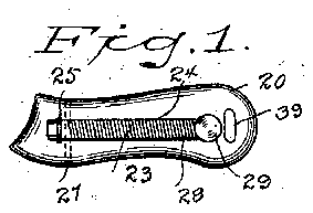
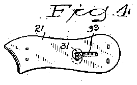
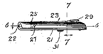
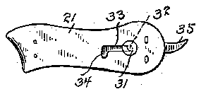
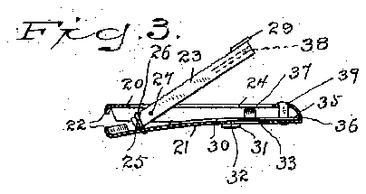
In the accompanying drawings, forming part of this specification, in which like characters of reference indicate the same parts, Figure 1 is a plan view of my novel nail-clipper in closed position; Fig. 2, an edge view in the closed position; Fig. 3, a longitudinal section on the line indicated by 3 3 in Fig.v
7, the cutting-jaws and operating-lever being in the open position; Fig. 4, an inverted plan view corresponding with Fig. 1; Fig. 5,
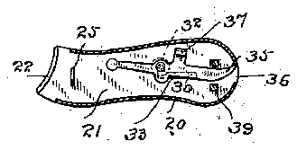
a similar view showing the nail-cleaner pro-' jected; Fig. 6, a horizontal section on the line 6 6 in Fig. 2, the catch on the slide be ing at the releasing position; and Fig. 7 is a transverse section on the line 7 7 in Fig. 2.
The body of my novel nail-clipper consists of two members 20 and 21, which for convenience I will'term the upper and lower members, respectively. This body may be made from one piece of spring metal or of two pieces rigidly secured together, as may be preferred,and either memberor both members maybe spring members. Ordinarily, however, member 20 will be made relatively rigid and member 21 sufficiently resilient to throw the cutters or cutting-jaws 22, carried by the free ends of the members, to the open position.
23 denotes the operating-lever, which is pivoted=in a slot 24in the upper member. The operating-lever is shown as pivoted on a transverse pin 27, which passes through the lever and through the upper member on opposite sides of the slot. At the forward end of the operating-lever is a transverse groove 26 to enable it to engage a yoke 25, which is rigidly secured to the lower member.
28 denotes a nail-file, which I preferably provide on the outer face of the operatinglever, and 29 a finger-piece at the free end of said lever, whichl' preferably provide for convenience in operation.
30 denotes a ,slid euwhich lies on the inner side of member 21 and'iscontrolled by means of a finger-piece 31', having a shank 32, which extends through an L-shaped slot in said member 21 and is riveted to the slide. For convenience in description I will designate the longitudinal portion of the slot by 33 and the transverse portion of said slot by 34:. The essential features of the slide are a nailone side of the operating-lever, as clearly shown in Fig. 7.
The operation of the implement will be readily understood from the drawings. Suppose the implement to be in the closed position and that it is desired to use the nailcleaner. The operator projects it, as in Fig. 5, by moving shank 32 by means of the finger-piece outward in slot 33, catch 37 sliding along in groove 38 and retaining the operating-lever in the closed position. As soon as the operator is through usingthe nail-cleaner he retracts it'by moving the shankinward along slot 33, the normal position of the shank and finger-piece when the'impleme'nt is not in use being at the angle of the slot or slots, as shown in full lines in Fig. 4. To release the operating-lever for use, as in Fig. 3, the operator by means of the finger-piece moves shank 32 outward in transverse slot 34that is, from the position shown in full lines in Fig. 4 to the position shown in dotted lines in Fig. 4 and also shown in Fig. 6. This moves catch 37 backward out of groove 38, and the resiliency of the members instantly throws the operating-lever upward and the cutting-jaws apart in position for use, as in Fig. 3.
The members are shown as rigidly secured together at the base by means of a U-shaped rivet 39, the sides of which lie on opposite sides of the nail-cleaner, as clearly shown in Fig. 6.
Having thus described my invention, I claim 1. A finger-nail clipper comprising members provided with cutting-jaws, an operating-lever pivoted to one of said members and engaging the other member, and a slide provided with a nail-cleaner and having a catch for retaining the operating-lever in the closed position.
2. A finger-nail clipper comprising members provided with cutting-jaws, an operating-lever pivoted to one of said members and engaging the other member, a slide provided with a nail-cleaner, and a catch for retaining the operating-lever in the closed position and means for operating said slide to lock or release the operating-lever and to project the nail-cleaner without releasing the operatinglever.
3. A finger-nail clipper comprising members provided with cutting-jaws, one of said members having connected slots lying at an angle to each other, an operating-lever pivoted to one of said members and engaging the other member, a slide provided with a nail-cleaner and a catch for retaining the operating-lever in the closed position, a shank extending through the slots and attached to the slide and an external finger-piece upon the shank whereby the slide may be operated to lock or release the operating-lever and to project or retract the nail-cleaner.
4. A finger-nail clipper comprising members provided with cutting-jaws, one of said members having connected slots lying at an angle to each other, an operating-lever pivoted to one of said members and engaging the other member and having a groove 38, a slide provided with a nail-cleaner and a catch adapted to engage said groove, a shank extending through the slots and attached to the slide whereby said slide may be operated to lock or release the operating-lever or to project or retract the slide.
In testimony whereof I aflix my signature in presence of two Witnesses.
JOHN C. ERNST.
Witnesses:
O. S. Boins, R. R. HEALEY.