

- 1leg
- 2sliding piece
- 3pin
- 4recess
- 11 see figs
- 13 see figs
- 74head or .knob
Description
PATENTED JULY 28, 1903 E. KAUFMANN. IMPLEMENT FOR THE NAILS.
APPLICATION FILED NOV. 14, 1902.
N0 MODEL UNITED STATES Patented July 28, 1903. i
PATENT @FFICE.
IMPLEMENT FOR THE NAILS.
SPECIFICATION forming part of Letters Patent No. 734,715, dated July 28, 1903.
Application filed November 14:, 1902. Serial No. 131,328. (No model.)
To all whom it nutty concern.
Be it known that I, ERNST KAUFMANN, a subject of the German Emperor, residing at Solingen, in the German Empire, have invented certain new and usefulImprovements in Implements for the Nails, of which the following is a specification.
The present invention relates to a new or improved implement for cutting, paring, filing, and performing like operations on the nails, corns, and the like, and has forits object to provide an extremely-handy device, more particularly adapted for the care of the finger and toe nails and for removing hardened skin (corns) from the feet, and which is at the same time capable of being readily carried in a small pocket in a garment. To this end a nail-cutter is provided with a nailfile and nail-cleaning implement, a knife blade, and the like.
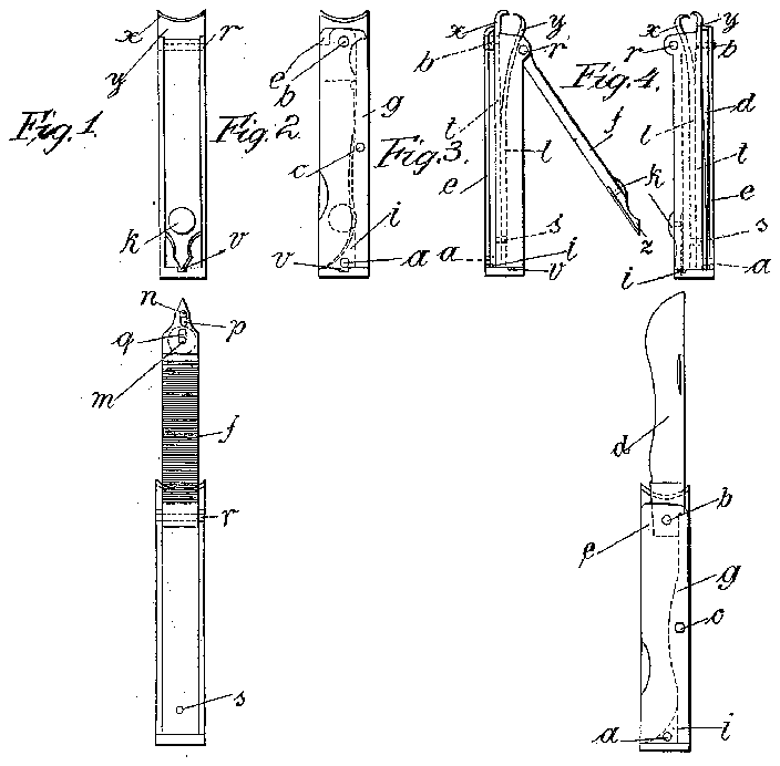
In the accompanying drawings, which illustrate, by way of example, two methods of carrying the invention into effect, Figures 1, 2,
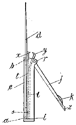
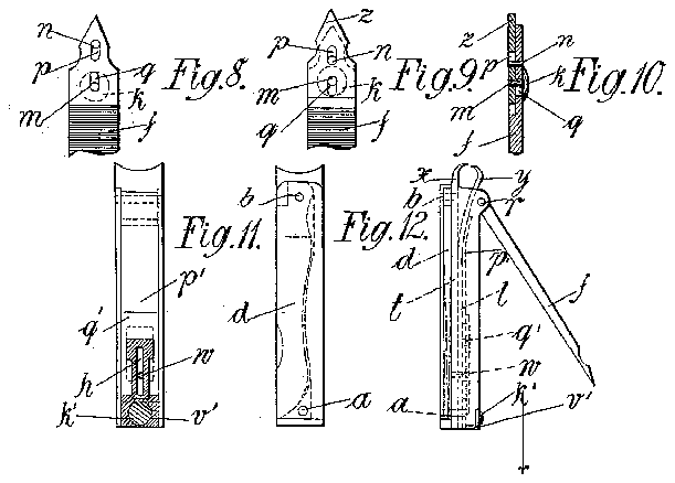
t and 4 are views in front, back, and side elevations, respectively, of the implement in the closed state. Figs. 3, 5, 6, and 7 are views of the implement with its parts in various positions. Figs. 8, 9, and 1-0 are broken detail views on an enlarged scale; and Figs. 11,
toward each other to abut or close onto each other, or, as shown in Fig. 4, to overlap each other. The two legs near their lower ends are connected together by a pin 3 and are situated in a prism-shaped box, to one side e of which the leg t is rigidly connected by the studs. a and b. The'stud I) also forms the pivot of a knife-blade d, which is acted on by a spring g, that is itself rigidly fixed to the side e by means of the stud c, Fig. 7. Opposite the wall e is a part f, which may be designated as the lid of the box. This partfis pivoted on the stud r. This part is preferably formed as a file and provided with a nail-cleaning device. The head of the part f, which is pivoted on the stud r, is so shaped or so pivoted as to act as an eccentric whereby the said head will move the elastic leg Z toward the fixed leg, when the partfis moved out of the position shown in Fig. 3 into the position shown in Fig. 4, and vice versa. That end of the part f which carries the nailcleaning implement is' provided with the closing device, that holds the said part in the position shown in Fig. 4. The closing device consists of a small sliding piece 2, the point of which is pressed into a recess 4; in the bottom 1; of the box. The sliding piecez is connected by means of a pin m with a head 70, that is formed on the outer side of the part Th is pin on is guided in the recess q in the part f, Figs. 8, 9, and 10. A further guidance is effected by arranging a stud n so as to project from the point of the partfinto a slot 19 in the sliding piece 2. If the head or .knob 74:, Fig. 4, be pushed in the direction of the cutting-faces m and y, the point of the sliding piece .2 will move out of its recess '0 and the leg 1 will now by reason of its elas .ticity force open the party, Fig. 3. Theimplement in this position can then be used as a nail-cutter. If the partfbe opened into the position shown in Fig. 5, in which it is quitefixed, then the implement can be used for filing the nails after they have been cut.
Fig. 7 shows the manner in which, the implement may also be used as an ordinary knife. It is obvious that the bottom team also be utilized for some purpose, such as a seal, polishing-surface, or the like.
' In order to render the action of the nailcutter more efiective, the catch or device for locking the file may also be so arranged as to provide means for transforming the leverage of the file into a comparatively powerful force acting upon the elastic leg Z. For this purpose the bottom t' of the form of implement shown in Figs. 1 to 10 is removed and in its stead there is provided a sliding part n, (see Figs 11 and 13,) L shape in cross-section. This part carries on its shorter leg a knob is for the purpose of more readily operating the same. Thelonger leg of the sliding part v is formed approximately of an I shape and has a slot h, by means of which the sliding part is guided on astud w. The stud w serves to attach a small plate q on the leg Z in such a manner as to allow one leg of the part c and another sliding part 13 to move between the leg 1 and the small plate q. The sliding part 19 embraces the I-shaped leg of the part b in such a manner that it is moved along by the part c in certain positions of the latter. Further, the sliding part is provided with a thickened border at its end, which is bent away somewhat. When the implement is closed, the point of the partf projects into the recess in the L-shaped part b. If the knob 70 be pressed downward, (in the direction of the arrow,) the partf will be forced out by reason of the elasticity of the leg Z. Then if the part '0 be again pushed upward contrary to the direction of the arrow and beyond the initial position the plate 19' will be moved therewith, and its thickened border or edge will be pushed under the pivotal point of the partf. It is obvious that this will increase the ratio between the power exerted at the partfand that exerted between the cutting-faces a: and y as compared with the arrangement first described. The locking of the file in the closed position is effected by a corresponding moving back of the part c.
What I claim, and desire to secure by Letters Patent ot the United States, is
1. A device of the class described comprising a case, a jaw fixed in the case, a movable jaw in the case for cooperation with the fixed jaw and a lid for the case constructed and arranged to operate and release the movable jaw when moved into and out of closing position.
2. A device of the class described comprising a case, a fixed jaw in the case, a movable jaw in the case disposed to cooperate with the fixed jaw, a pivoted lid for the case constructed and arranged to operate and release the movable jaw when moved into and out of closing position, said case having a keeper, and a latch carried by the lid and adapted for engagement with the keeper to hold the lid and jaws in closed positions.
3. A device of the class described comprising a case, a fixed jaw in the case, a movable jaw in the case disposed to cooperate with the fixed jaw, a pivoted lid for the case having a cam disposed for engagement with the movable jaw to operate it when the lid is moved into closed position and a latch carried by the lid for holding it in closed position and having a portion disposed to enter between the cam and the movable jaw when the latch is in disengaged position.
4. A device of the class described comprising a case, a fixed jaw in the case, a movable jaw in the case for cooperation with the fixed jaw and a lid for the case constructed and arranged to operate and release the movable jaw when moved into and out of closing position, said lid having a file upon one face and having a nail-cleaning device at its free end.
In testimony whereof I have hereunto set my hand in the presence of two witnesses.
ERNST KAUFMANN.
Witnesses:
PAUL SCHIMMELBUSOH, VICTOR W. HELDT.