- 3ears
- 7member
- 9ears
- 11spring
- 12operating-lever
- 13ears
- 14pin
- 16end
- 18notch
- 19lock
- 20pivot
- 21free end
Description
` PATENTES) JAN. 5, 1904.
H. C. HART.
FINGER NAIL GLIPPER.
MPLIMTIoN FILED MAY 29, 1903..
N0 MODEL.
WJTNESSES- l pfui Nanms mans ca, PHO-ranma., wAsHxruwNr u. c
- bers locked together.
UNITED STATESr Patented January 5, 1904.
HUBERT C. HART, OF IUNIONVILLE, CONNECTICUT.
FflNeER-NAIL CUPPER.
SPECIFICATIGN forming part of Letters Patent No. 748,864, dated January 5, 1904.
Application filed May 29, 1903. Serial No. 159.353. (N o model.)
To @ZZ whom it may concern:
Beit known that I, HUBERT C. HART, a citizen of the United States, residing at Unionville, in the county of Hartford and State of Connecticut, have invented new and useful Improvements in Finger Nail Clippers, of which the following is a specification.
i This invention relates to improvements in a iinger-nail-clipping device; and it has for its object to provide a stationary cutting mem ber, a movable and spring-actuated cutting member, an operating-lever iitting under the movable cutting-lever, and a look which ts a notch in the end of the movable cutting-lever to effectually close the cutters when the device is not in use.
Many other objects and advantages will be hereinafter explained and be particularly pointed out in the claims.
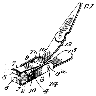
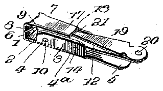
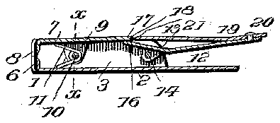
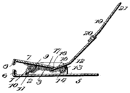
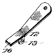
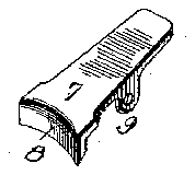
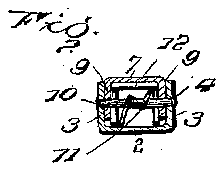
In the drawings, Figure 1 is a perspective view of myimproved finger-nail-clipping device,showingtheeutting membersopen. Fig.` 2 is a similar View showing the cutting mem- Fig. 3 is a vertical section of Fig. 2. Fig. tis a similar viewof Fig. 1. Fig. 5 is a detail perspective view of the operating-kever. Fig. 6 is a similar view of the movable cutter. Fig, 7 is a transverse section on the line :c .fr of Fig. 3. Fig. 8 is an enlarged detail section of the end of the lock and its engaging notch.
The numeral 1 represents a stationary cut-l ter, and it comprises a base portion 2, having along its edges a pair of ears 3, provided with two sets of perforations 4 4a, while the base beyond the ears forms a finger-piece 5. The opposite end of the base is bent at right angles, and its upper edge is curved and sharpened to form the stationary cutting member 6.
7 indicates the movable cutting member, and it consists of a plate bent at one end at an angle, which end is curved and sharpened to form the movable cutting edge 8, and extending .downwardly from the sides of the member 7 are perforated ears 9. The member '7 is fitted within the embrace of the ears 3 3, the perforations in the ears 9 registering with the perforations et of the ears 3. A pin l0 is passed through the forward openings in the ears, and mounted on the pin is a spring 11, bent to exert its force tonormally open the movable member for the ready insertion of the finger-nail.
The operating-lever 12 has formed with it, a short distance from one end, depending perforated ears 13, while its opposite end forms a convenient purchase for a persons thumb. The ears 13 are embraced also by the ears 3 3, and their openings register with the openings 4, through which a pin 14 is passed. f
The operation of my improved finger-nail cutter as thus far described is lsubstantially as follows: Presuming the two cutting members to have been assembled with relation to each other as described, it will be observed that the end 16 of the operating-lever tits under the end 17 of4 the movablecutting member 7, and as the spring tends to throw' the cutting edges apart, and hence depress the end 16 of lever l2, obviously the normal position of the outer end of the ,operating-lever and the linger-piece 5 is open. The action then in cutting the nger-nail is a simple one. The device is grasped between the fingers and by a slight compression of the lever 12 it acts to positively close the cutting edges, and by reason of the relation existing between the movable cutting member 7 and the operating-lever 12 the edges 6 and 8 are brought into contact with each other with very little force. I
When the device is not in use and it is car-l ried in a persons pocket, it would be a very awkward thing to carry were it permitted to remain open, and to meet this emergency I provide a unique locking device to eliectually close the cutting edges against being opened by any ordinary knock or the like. To this endl provide a notch 18 in the outer end of the cutting member 7, and coacting with this ,notch is a lock 19, pivoted at 20 to the operating-lever 12. The free end of the. lock 19 is beveled to engage the notch 18 when the device is locked. Should a person desire to lock the cutting members, the lock 19 is turned on its pivot 20 to cause the free end 21 to enter the notch, whereupon the device becomes' inoperative, as shown in Figs. 2 and 3. This is due to the fact that lock 19 is carried by the operating-lever, and as the length of the lock from its pivot to the outer end is suficient to prevent the spring lowering the end IOC 17 of the member 7 it can be readily seen that no movement of the cutters can take place. To unlock the device, the lock is turned 'on its pivot 20, as shown in Fig. 1.
My invention is neat in appearance and decidedly compact in form. Moreover, the spring of the metal of the operating-lever is sufficient to permit of its being slightly depressed, whereby the friction between the lock and its notch can be reduced in order that said lock may be conveniently and readily disengaged.
What I claim as new is- 1. A nger-nail-clipping device comprising a stationary cutting member, a movable cutting member, means pivotally connecting the two cutting members, a spring to normally open the cutters, an operating-lever whose end fits under the movable cutting member to normally open the said lever from the stationary cutting member, and mechanisms carp ried by said lever to engage the movable cutting member and lock the cutters together, substantially as described.
a stationary and movable cutter, the latter having a notch, an operating-lever in engagement with the movable cutter, and'a lock carried by said lever which engages the'notch in the movable cutter to lock the cutters together, substantially as described.
3. A finger-nail cutter comprising a stationary and a movable cutter,- the latter having a notch in its end, an operating-lever pivoted to the stationary cutter, and a lock pivoted to the operating-lever, the free end of which engages the notch in the movable cutter to lock the cutters together, substantially as described.
4. Anger-nail-clippingdevice,comprising a stationary cutting member having perforated ears, a movable cutting member having ears, a notch in the end of said member, a pin connecting the ears of the stationary and movable cutting members, a spring to normally hold the two members apart, an operating-lever having perforated ears, a pin engaging the ears of the said lever and the stationary cutting member, the end of the cutting-lever fitting under the end of the movable cutting member, and a lock pivoted to the operating-lever, the free end of said lock adapted to engage the notch in the movable member to lock the cutters together, substantially as described.
5. Afinger-nail-clipping device,comprising a pair of cutters, one of which is movable, and a pivoted locking device engaging the l movable cutter and adapted to close said cutters, said locking device being mounted 2. Anger-nail-clippingdevice,comprising 3 whereby a slight compression of its pivoted end will relieve the friction of the lockingpoint from the movable cutter and permit the cutters to be opened, substantially as described.
In testimony whereof I have signed my name to this specification in the presence of two subscribing witnesses.
HUBERT C. HART. Witnesses:
DENIZA MATTHEWS, JNO. IMIRIE..