
- 2flanges
- 3spring
- 4plate
- 5be
- 9line
- 19shallow notch
- 20hook which
- 30opposite end or
Description
No. 766,859. PATENTED AUG. 9,1904. H. WILGOX.
. MANIGURE TOOL.
APPLICATION FILED 00120. 1903.
1910 MODEL.
UNITED STATEs Patented August 9, 1904.
PATENT OFFICE.
HENRY WILCOX, OF NEFVARK, NEW JERSEY, ASSIGNOR, BY MESNE AS- SIGNMENTS, TO SCHATZ HARDWARE MANUFACTURING COMPANY, OF WEST VIRGINIA, OF CHAPPAQUA, NE YORK.
MANmuRE-TooL.
SPECIFICATION forming part of Letters Patent No. 766,859, dated August 9, 1904. Application filed October 20, 1903. Serial No. 177,75I. (N model.)
To all whom it nmiy cone/37 1i:
Be it known that I, HENEY ILcoX, a citizen of the United States, residing at 74 Monmouth street, Newark, county of Essex, State of New Jersey, have invented certain new and useful Improvements in lVIanicure-Qloole, fully described and represented in the following specificationand the accompanying drawings, forming a part of the same.
The object of the present invention is to facilitate the manufacture and improve the construction of that class of nail-clippers in which two levers are pivoted near one end and provided at such end with the jaws for clipping the finger-nail.
In the present invention a nail-cleaner is pivoted upon the rear cnd'oi' the upper lever and furnished with stops to hold it in its open and closed positions and with a hook which 20. projects at its rear end when in its closed position to engage a recurved spring attached to the lower lever. l/Vhen the nail-cleaner is closed, the hook can be engaged with the spring by merely pressing the levers together,
which looks themin an inoperative position for carrying in the pocket. The nail-cleaner serves as a handle to detach the hook from the end of the spring when it is desired to open the levers and operate the clipper.
0 I The invention includes a stop for the cleaner when shut, a stop for the cleaner when open, a particular construction for the spring and for securing the same upon the lower lever, and a particular arrangement of the spring 3 5 for closing the opening in the frame of the rear lever to form a bearing-seat for the fingers.
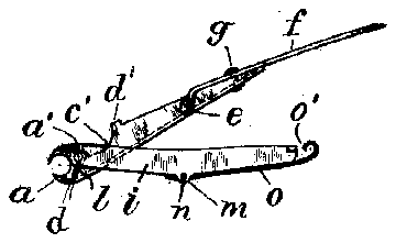
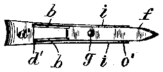
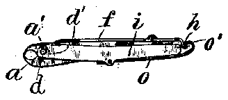
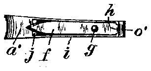
In the annexed drawings, Figure 1 isaside elevation of the clipper entirely opened in 4 readiness for use. Fig. 2 a plan of the upper side of the same. Fig. 3 is an edge view of the clipper closed and the levers locked. Fig. & is a plan of the upper side of the same, showing the nail-cleaner in its closed position. Fig. 5 shows the under side of the clipper when locked. Fig. 6 shows the lower lover of the clipper separated. from the other parts, and Fig. 7 shows the upper side of the spring which is secured upon such lever.
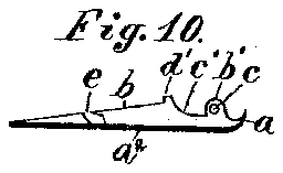
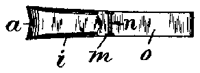
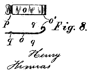
Fig. 8 is a longitudinal section of the spring. 5 Fig. 9 is a transverse section on line 9 9 in Fig. 8, and F ig. 10 is a longitudinal section oi. the upper lever looking toward the edge which clears the hook on' the nail-cleaner.
Each of the levers is made of one piece of sheet metal stamped to the desired form, the upper lever having a plate at extending its whole length, with the jaw (z bent upwardly at one end and. side flanges 7) also bent upwardly and provided with lugs 6, having 6 pivot holes 0 for the hinge-rivet (Z. The flanges I) are formed with notch c in their edges adjacent to the lugs for the purpose hereinafter described. One of the side flanges b is formed with a notch c for apurpose to be 5 described. The lower lever is likewise stamped of sheet metahwith downwardly-bent flanges i, the upper plate of the lever being wholly cut away by a slot 7' to permit the insertion and movement of the upper lever, excepting a cross-piece 7: at the rear end of the lever to hold the side flanges together, and at the front end where provided with the cutting-jaw and with the jaw-plate (1/, which is extended a little back of the hinge-pin (Z.
. The nail-cleaner fis formed as a two-armed lever pivoted by a rivet g to turn horizontally upon the top of the upper lever and has the pointed end (which serves as a nail-cleaner) of greater length than the opposite end or 30 tailpiece, which is bent downward at the end, and the projection provided at its extremity with a catch formed as an upwardly-turned catch-hook /1.. The projection with catch-hook 72 is adapted to enter the notch a and is made of 8 5 suitable width to strike the opposite unperforated flange b, which serves as a stop to hold the nail-cleaner extended, as shown in Figs.
1 and 2.
The flange having the notch a is provided '9 adjacent to the pivot-holes c with an upwardlyprojccting stud ti, which serves as a stop to set the nail-cleaner parallel with the body 01' the upper lever when turned inwardly, as shown in Figs. 3 and 4E.
The extension of the plate a backwardly from the jaw is to form a stop for the opening movement of the levers, which is eflected in pressing the levers together.
by the contact of such plate with the bottoms of the notches 0 upon the flanges b, as shown in Fig. 1.
The lever is also provided with holes for the hinge-pin (Z, and the usual spring [is wound upon the pin and its ends extended against the plates of the upper and lower jaws to hold the levers separated, as shown in Fig. 1 and Fig. 6.
The lower flanges z' are formed with ears on to receive a cross-pin 9t, and a spring-plate 0 is formed to lie upon the lower edges of the flanges t' and provided with notches p in the edges to embrace the ears m.
The spring-plate 0 is provided with a transverse indentation q to lie beneath the pin a and is bent to press normally upward against the edges of the flanges 2'. The spring thus lies on the outside of the lower lever and covers the open space between the flanges and serves to form a seat to support the fingers The rear end 0 of the spring is recurved and bent downwardly and formed with shallow notch 19' to engage the hook 7L upon the tailpiece of the nail-cleaner, which hook is made narrower than the body of the nail-cleaner, as shown in Fig. 2, to contact with one of theflanges b of the upper lever in forming a stop for the opened cleaner.
When the nail-cleaner is turned inwardly, as shown in Figs. 2 and 3, the jaws may be pressed together and the hook it snapped beneath the recurved end 0 of the spring 0, where it engages the notch p. The notch holds the cleaner from any involuntary movement or turning upon its pivot, but does not prevent the moving of the nail-cleaner around its pivot by the use of a little force when it is desired to open the nail-cleaner for using the clipper, as shown in Fig. 1. WVhen thus moved, the hook l2. crowds the curved end 0 of its engaging spring upwardly enough to move past the same. When thus turned, one finger can be laid upon the top of the nailcleaner and the other upon the body of the spring 0, which serves as a seat or thumbpiece for the finger when pressing the levers together for using the clipper in the ordinary manner.
The parts for my nail-clipper canbe cheaply made by suitable tools, and the device itself is convenient and practicable for operation.
Having thus set forth the nature of the invention, what is claimed herein is 1. In'anail-clipper having the levers formed of sheet metal, the combination of two levers having each a jaw at the forward end and hinged by the rivet (Z adjacent to such jaws, the lower leverhaving the flanges z' bent downwardly and connected solely at the opposite ends by plate a and the cross-piece k, the upper lever formed with a plate (4 along its lower side terminated at the front in the jaw a with the flanges Z) and lugs b bent upwardly ,two levers having each a jaw at the forward end and hinged by the rivet (Z adjacent to such jaws, of a nail-cleaner formed as a two-armed lever pivoted to turn horizontally upon the top of the upper lever, the shorter arm forming a tailpiece with catch at the end, and the outer side of the lower lever having a leaf-spring attached thereto and having a recurved bend at its free end arranged to engage the catch upon the tailpiece to lock the levers together.
3. In a nail-clipper having levers formed of sheet metal, provided each with a jaw atthe forward end and hinged by'the rivet cZ adjacent to such jaws, the combination, with the upper lever having upwardly-bent flanges 6 one of them provided with the notch e, of the nail-cleaner f pivoted to turn horizontally upon the top of said lever and having the catch-hook adapted to enter the notch to arrest the movement, andthe lower lever having a leaf-spring attached to its outer side with its free end adapted to engage the catch-hook upon the nail-cleaner when-turned to the rear end of the clipper, the jaws being unlocked by turning the nail-cleaner horizontally upon its pivot, g to disengage the catch fromthe leaf-spring.
. I. In a nail-clipper having levers formed of sheet metal, the combination, with the upper lever having upwardly-bent flanges I; one of them provided with the stud cl and notch e, of the nail-cleaner f pivoted to turn horizontally upon the top of said leverand having a tailpiece with hook h adapted to enter the notch to form a stop, and the nail-cleaner being adapted to contact with the stud d to set the cleaner in an inoperative position, and the lower'lever having a spring to engage said hook when turned to the rear end of the lever.
5. In a nail-clipper having levers with a spring to separate the same, the combination, with the upper lever having the nail-cleaner f provided with tailpiece having upwardlybent hook /b as set forth, of the lower lever having the flanges provided with ears m and transverse pin 72, and the spring-plate 0 fitted to the edges of the flanges and notched to embrace the ears m, and grooved to fit beneath the pin a, and having its rear end recurved downwardly to engage the hook it upon the nail-cleaner to lock the levers together.
In testimony whereof I have hereunto set my hand in the presence of two subscribing witnesses.
HENRY WILOOX. Witnesses:
THOMAS S. CRANE, L. LEE.
IIO

