
- 2i
- 5tongue
Description
No. 770,032. PATENTED SEPT. 13, 1904. H. WILGOX.
MANIGURE NAIL CLIPPER.
APPLIOATION FILED MAY 31, 1904.
N0 MODEL.
diff/ 66 if J J44 W8 44 5-01..
UNITED STATES Patented September 13, 1904.
PATENT OFFICE.
HENRY VVILCOX, OF NEWARK, NEW JERSEY, ASSIGNOR TO WILOOX NOVELTY COMPANY, OF NEWVARK, NEW JERSEY, A CORPORATION OF NEW JERSEY.
IVIANICURE NAIL-CLIPPER.
SPECIFICATION forming part of Letters Patent No. 770,032, dated September 13, 1904:.
Application filed May 31, 1904. Serial No. 210,366- (No model.)
To all whom it may concern:
Be it known that I, HENRY WILoox, a citizen of the United States, whose residence and post-office address is 7A Monmouth street, Newark, county of Essex, State of New Jersey, have invented certain new and useful Improvements in Manicure Nail-Clippers, fully described and represented in the following specification and the accompanying drawings, forming a part of the same.
The object of the present invention is to furnish a means of constructing a nail -olipper with levers formed of fiat pieces or leaves of sheet metal which can be made in a single op eration by punching.
The invention includes a particular construction for the levers and for the means of securing the jaws in the levers and other details of construction, which are set forth in the following description and claims.
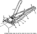
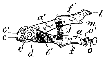
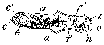
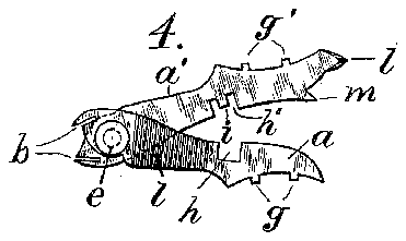
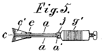
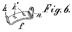
The construction will be understood by reference to the annexed drawings, in which- Figure l is a side elevation of the nail-cutter with the arms and jaws open. Fig. 2 is a side view of the same with the arms closed and locked together. Fig. 3 is a plan of the lower lever and jaw with the upper lever and jaw removed. Fig. 4 is an elevation of the levers with the attachments removed. Fig. 5 is a plan of the nail-cutter with the parts in the position shown in Fig. 2. Fig. 6 is a perspective view of the thumb-piece carryingthe lug for the locking-screw. Fig. 7 isa plan of the upper cutter, and Fig. 8 an edge view of the same. Fig. 9 is a plan of the lower cutter, and Fig. 10 is an edge view of the same.
Fig. 11 is a front view of the jaws partlyclosed in the act of cutting.
a designates the two leaves of the lower lever and a the leaf of the upper lever fitted between the same and jointed thereto near the forward end by pivot e. Notches bare formed in the leaves forward of the pivot and inclined toward one another at their outer ends, and jaw-blades or cutters c 0 are fitted to the said notches and are preferably formed with notches 7), which embrace the sides of the leaves at the rear end of each cutter. The
jaw-blade c is formed with two notches to embrace the fiat sides of the two leaves a, which form the lower lever, and a tongue 5 between the two notches serves to space the leaves at a suitable distance apart. Shoulders d are shown formed upon the outer sides of the leaves a little in the rear of the pivot e, at a suitable point to contact with the rear ends of the jaw-blades or cutters c 0 when the cutters are opened. The contact of the jawblades with the shoulders forms a stop which serves to limit the opening movement of the jaws. Studs g g are projected, respectively, from the outer edges of the lower and upper levers, and thumb-pieces ff are formed with holes to fit upon the said studs, by which they are riveted to the levers.
The holes is in the lower thumb-piece are arranged to space the leaves of the lower lever a little farther apart at the rear ends than at the forward ends, which permits the upper lever to play freely between such leaves. The outer edges of the leaves are concaved and the thumb-piece bent to fit the curvature of the same. The upper lever (that which carries the lower jaw 0 at its forward end) is provided at its extreme rear end with a nailcleaning blade or point Z, and the outer sides of the leaves a in the rear of the pivot are formed with file-teeth Z. Notches h it are formed in the lower and upper levers to receive the ends of a spiral spring 7', and a stud is formed in the center of the upper notch to center the spring therein. The lower thumb-piece g is formed with an integral stud it, which is bent forwardly between the leaves a into the center of the notch it to center the lower end of the spring therein. The rear end of the thumb-piece f is formed with an integral lug a, and a screw 0 is fitted through such lug to move longitudinally of the levers and held in the lug by a cross-pin 0. A toe m is formed upon the upper lever adjacent to the point of the screw and is projected rearwardly, so that when the screw is engaged with the same it holds the levers locked together in opposition to the tension of the spring j.
The thumb-pieces are roughened upon the outer side, which is readily effected by stamping, to prevent the fingers from slipping when operating the cutter. The lower cuttingblade 0 is projected a little beyond the upper cutting-blade c, and the lower cutter is formed upon the end of such blade, so that the upper cutter can pass within the same to produce a shearing cut. The edges of the opposed cutters are inclined sufficiently away from one another, as shown in Fig. 11, so that the cutters engage first at one end, and thus operate upon the nail progressively, like a scissors. The operation of the cutter is thus very smooth and easy.
All the parts, excepting the screw and rivet, are formed by stamping from single thicknesses of sheet metal, and the device is thus very cheaply constructed, while it is most eflicient in operation.
Having thus set forth the nature of the invention, what is claimed herein is 1. The nail-clipper having the sheet-metal lever-arms pivoted near their forward ends and formed respectively of single and double flat leaves, provided near their rear ends with thumb-pieces, and at the forward ends with inclined notches, and jaw blades provided with the longitudinal notches b and with the jaws 0, 0 bent in opposite directions to operate with one another, the jaw-blades being inserted in the inclined notches on the leverarms, and the notches of the jaw-blades embracing the sides of such lever-arms, whereby they are held accurately in the desired position. i
2. The nail-clipper having the sheet-metal lever-arms pivoted near their forward ends and formed respectively of single and double flat leaves, provided near their rear ends with thumb-pieces, and at the forward ends with inclined notches and with the shoulders (Z as set forth, and jaw-blades having longitudinal notches secured in the notches of the arms and arranged to contact with the said shoulders to limit the opening movement.
3. The nail-clipper having the sheet-metal lever-arms pivoted near their forward ends and formed respectively of single and double flat leaves provided near their rear ends with thumb-pieces and at the forward ends with inclined notches, a spring to separate the jaws, jaw-blades secured in the notches, a rearwardly-projecting toe upon one of the levers and a longitudinally-adjustable screw upon the other lever adapted to engage such toe to hold the jaws closed.
4. The nail-clipper having the sheet-metal lever-arms pivoted near their forward ends and formed respectively of single and double flat leaves provided near their rear ends with thumb-pieces and at the forward ends with inclined notches, a spring to separate the jaws, jawblades secured in the notches, a rearwardly-projecting toe upon one of the levers, a transverse lug upon the opposite lever adjacent to such toe, a longitudinallymovable screw in such lug to engage the toe, and means for holding the screw rotatably in the lug, as and for the purpose set forth.
5. The nail-clipper having the sheet-metal lever-arms pivoted near their forward ends and formed respectively of single and double flat leaves, thumb-pieces secured upon the outer sides of the leaves, a rearwardly-projecting toe upon one of the levers, a transverse lug at the rear end of the thumb-piece upon the opposite lever, and alongitudinallyadjustable screw fitted to such lug and adapted to engage the toe, as and for the purpose set forth.
6. The nail-clipper having the sheet-metal lever-arms pivoted near their forward ends and formed respectively of single and double fiat leaves, with notches in the rear of the pivots to receive a spiral spring, and the levers provided at the rear ends with thumbpieces and at the forward ends with inclined notches. jaw-blades secured in the notches and shaped to make a shearing cut, a stop to limit the opening of the jaws, a spiral spring fitted to the notches of the levers to press the levers apart, and means for centering the ends of the spring in such notches, substantially as herein set forth.
7. The nail-clipper having the sheet-metal lever-arms pivoted near their forward ends and formed respectively of single and double fiat leaves, with notches in the rear of the pivots to receive a spiral spring, and thelevers provided at the rear ends with thumbpieces and at the forward ends with inclined notches, jaw-pieces secured in the notches and shaped to make a shearing cut, a stop to limit the opening of the jaws, a spiral spring fitted to the notches of the levers, means for centering the ends of the spring in such notches, and means for locking the levers together when desired.
In testimony whereof I have hereunto set my hand in the presence of two subscribing witnesses.
HENRY WILCOX. Witnesses:
THoMAs S. CRANE, L. LEE.

