- 1member
- 2opening
- 3edge
- 4pintle
- 6cleaner
- 10finger-piece
- 11member
- 12handle
- 13opening
- 15lug
- 16spring
- 22line
Description
NTTED STATES Patented February 14, 1905.
PATENT OFFICE.
HUBERT C. HART, OF UNIONVILLE, CONNECTICUT, ASSIGNOR TO THE H. C. COOK COMPANY, OE ANSONIA, CONNECTICUT.
NAIL-CLIPPER.
SPECIFICATION forming part of Letters Patent N0. 782,654, dated February 14, 1905.
Application leC September 19, 1904. Serial No. 225,069.-
To all whom, it may concern:
Bev it known that I, HUBERT C. HART, acitizen of the United States, residing at Unionville, in the county of Hartford and State of Connecticut, have invented new and useful Improvements in Nail-Clippers, of which the following is a specification.
This invention relates to improvements in finger-nail clippers.
The object of the invention is to provide a nail-clipper having concealed means for locking the clipper-jaws to prevent the opening of the latter when not in use in a persons pocket. A
Many other objects and advantages will be hereinafter referred to, and pointed out particularly in the claims.
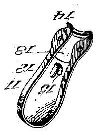
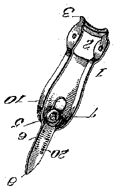
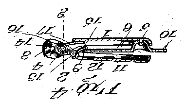
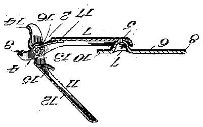
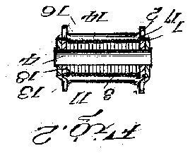
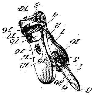
In the drawings, Figure 1 is a perspective view of my improved nail-clipper. Fig. 2 is a transverse section on the line 22, Fig. 4. Fig. 3 is a vertical section showing the clippers open. Fig. 4 is a similar view showing the clippers closed. Fig. 5 is a detail perspective View of one of the clipper members. Fig. 6 is a similar view showing the complementary member.
The numeral 1 represents a clipper member l provided with an opening 2 near its front end.
The end neXt the opening 2 is bent and sharpened to form a curved cutting edge 3, and the side walls of the opening connecting the edge 3 are perfo-rated to receive a pintle 1. At the opposite end of the member 1 is pivotally mounted by a rivet or the like 5 a linger-nail cleaner 6,which also forms a locking element. The cleaner 6 has'a depression at 7', in which is seated the pivot 5, and at the inner end the cleaner is pointed, as at 8, while its opposite end projects beyond the rivet andoutside the end of the member 1 to form a finger-piece 10. A second clipper member is indicated at 11, and it comprises a handle 12, provided with an opening 13, and at its front end the metal is bent and sharpened to form a curved cutting edge 14, corresponding in size and shape with the/edge 3. The side arms of the clipper member 11 are perforated to receive the pintle 4f, said side arms fitting in the opening 2 of the clipper member 1. In rear of the opening 13 a lug 15 is struck from the body of the metal and is in such position that when the two members are closed the pointed end of the cleaner 6 will engage it and prevent the members being opened. A spring 16 is coiled around the pintle 4, one end, 17, engaging the member 1 and the opposite end, 18, engaging the complementary member 11.
The parts assembled as set forth, the spring will normally hold the two clipper members apart, and upon squeezing them the cutting edges 3 and 14 are brought together and readily sever the finger-nail. If it be desired to lock the two clipper members together, they are closed and the cleaner 6 is turned on its pivot to bring the point into engagement with the lug and prevents the members being opened. To release the members, that the dep vice may be operated, the finger end of the cleaner is turned and the pointed end engaged from the lug 15 and the spring throws the members open.
The finger-nail cleaner may have a series of serrations 2O to form a file for the finger-nails When desired.
What I claim as new is 1. A. iinger-nail clipper comprising a pair of spring-actuated clipping members pivoted together, a lever vpivoted on the inner side of one of the clipper members, and a lug struck from the complementary member and projecting on the inner side thereof, the pivoted lever engaging the lug to lock the two members together, substantially as described.
2. A nger-nail clipper comprising a pair of spring-actuated clipping members pivoted together, a pointed lever pivoted on the inside of one of the clipping members, a lug on the inside of the complementary clipper member,
the pointed end of the lever engaging thelug to lock the clipper members together, substantially as described.
3. A finger-nail clipper comprising a pair of spring-actuated clipping members pivoted together, a lever pivoted on the inner side of one of the clipper members, and a flanged lug on the complementary member and projecting on the inner side thereof, the pivoted 1e- Ver engaging the flange of the lugto lock the IO two members together, substantially as described.
In testimony whereof I aiix my signature in presence of two subscribing witnesses.
'HUBERT' C. HART. Witnesses:
J No. IMIRIE, DENIZA J. MATTHEWS.

