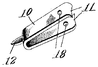
- 10yoke
- 11inwardly-facing cutting-jaws
- 12cleaning-point
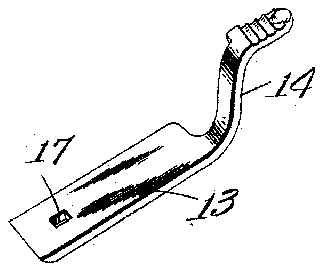
- 13side pieces
- 14crossing handles
- 16ring
- 17holes
- 18holes
- 19two pieces
Description
No. 796,389. PATENTBD AUG. 1, 1905. J. 1). WRIGHT, 9909).
L. M. WRIGHT, ADMINISTRATRIX.
FINGER NAIL CUTTER, CLEANER, AND FILE;
APPLIOATIOH TILED 1030.15, 1904.
UNITED STATES PATENT orrion.
JACOB D. WVRIGHT, OF WVORCESTER, MASSACHUSETTS; LAURAETTA M. WRIGHT ADMINISTRATRIX OF SAID JACOB D. WVRIGHT, DECEASED.
FINGER-NAIL CUTTER, CLEANER, AND FILE.
Application filed December 15, 1904. Serial No. 236,927.
To all whom it may concern:
Be it known that I, JACOB DVVRIGHT, a citizen of the United States, residing at Worcester, in the county of Worcester and State of Massachusetts, have invented a new and useful Finger-Nail Cutter, Cleaner, and File, of which the following is a specification.
This invention relates to a novel form of nippers which have been especially designed for use in a combined finger-nail cutter, cleaner, and file.
The especial object of this invention is to provide a form of nippers which will act with powerful leverage, which will present the cutting-jaws in convenient position to be sharpened or ground, and which will be especially adapted for use as a pocket toilet article.
To these ends this invention consists of the implement as an article of manufacture and of the combinations of parts as hereinafter described, and more particularly pointed out in the claims at the end of this specification.
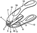
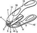
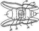
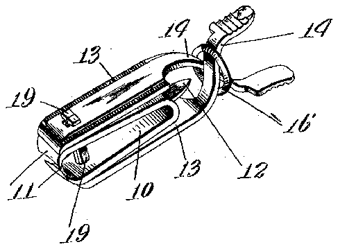
In the accompanying drawings, Figure 1 is a perspective view of the finger-nail cutter,
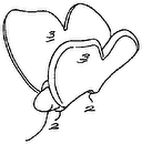
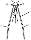
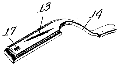
cleaner, and file constructed according to this invention; and Fig. 2 is a perspective view showing the several parts of the implement. A nippers constructed according to this invention comprises normally opening springpressed jaws, which are combined with a pinching-frame, the handles of which are adapted to be operated to close the jaws.
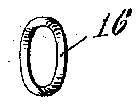
Referring to the accompanying drawings and in detail, a cutting implement constructed according to this invention, as herein illustrated, comprises a reversible yokelO, having inwardly-facing cutting-jaws 11 at one end and a cleaning-point 12 at its opposite end. The yoke 10 is reversibly mounted in a pinching-frame comprising side pieces 13, which have crossing handles 14:. These parts are held together by a single connection or double rivet, which extends through the holes 17 of the side pieces 13 of the pinching-frame and through holes 18 in the reversible yoke. This double rivet consists of two pieces 19, the lower ends of which are headed over or bent, as shown by dotted lines in Fig. 2. Fitted onto and holding the handles of the pinching-v frame is a ring 16, which prevents the frame from being displaced or pulled apart, while it does not interfere with the normal operation. In a complete implement as thus constructed Specification of Letters Patent.
Patented Aug. 1, 1905.
it will be seen that the pinching-frame is arranged to have a strong leverage engaging the cuttingjaws near their exact cutting edges, while at the same time the cuttingjaws themselves will project far enough so that their faces can be readily filed or ground when the implement is to be sharpened. When the implement is used in cutting, a strong cutting action will be secured, and as the cutting-jaws are carried by spring-arms the jaws will always approach each other with proper alinement.
The edges of the side pieces 13 of the pinching-frame are cut to form nail-files for rounding and smoothing the nails, while the yoke is reversible in its pinching-frame, so that it can present either the cleaning-point 12 or its cutting-jaws in position to be used.
I am aware that many changes may be made in the manufacture of implements according to this invention without departing from the scope thereof as expressed in the claims, and while my construction has been especially designed for use as a finger-nail cutter it is to be understood that I may embody my invention in cutting implements which are used for other purposes. I do not wish, therefore, to be limited to this particular construction; but
What I do claim, and desire to secure by Letters Patent of the United States, is-
1. In an implement of the kind described, the combination of a pinching-frame having extending handles, and a yoke reversibly mounted in the pinching-frame with cuttingjaws at one end, and a nail-cleaning point at the other end.
2. In an implement of the kind described, the combination of a pinching-frame comprising side pieces having extended crossing handles, a spring-yoke mounted in the pinchingframe with cutting-jaws at one end, and a rivet extending through said parts transversely to the cutting-jaws.
3. In an implement of the kind described, thecombination of a pinching-frame comprising side pieces having extended crossing handles, a ring preventing separation of said handles, a spring-yoke mounted in the pinching-frame, and having on tting-jaws at one end, and a transverse rivet holding said parts together.
4. In an implement of the kind described,
the combination of a pinching-frame compris- In testimony whereof I have hereunto set lng side pleces having extended crossing hanmy hand in the presence of tWo subscribing dles, a ring holding said handles from turn- Witnesses.
ing laterally, a spring-yoke having cutting- JACOB D. WRIGHT. jaws at one end, and a two-part rivet com- Witnesses: prising pieces having oppositely-bent headed LOUIS W. SOUTHGATE,
ends for holding the parts together. ANGIE M. GODDARD.
