- 2rivets
- 3pivot-pin
- 4rivets
- 5iitting within recesses
- 10blade
- 11arj
- 14lett hand j
Description
narra sfrafrirs OTTO KAMPFE, OF NEW YORK, N. Y.
NAIL-CLIPPER.
Specification of Letters Patent.
Patented March 12, 1907.
Application filed April 16, 1906. Serial No. 311,829.
10 all whom, t 77u14/ cm1/cern:
Be it known that I, OTTO KAMPFE, a citizen of the UnitedStates, residing at the borough of Brooklyn, Kings county, city and State of New York, have invented a new and useful Improvement in Nail- Clippers, of which the following is a specification.
This invention relates to an improved form of clipper for finger and toe nails. Hereton fore in manicuring instruments of this character the cutting-jaws have closed or shut down upon one another, severing and at the same time crushing the nails between their sharp and opposing edges, leaving more or less of a ragged edge; and the principal object of my invention is to so arrange the cutting-jaws as to provide a shearing cut similar to a scissors, so that in cutting the nails a clean cut is made.
In the device of my improvement I provide a base-plate and upturned inclined arms with a roller pivotally mounted between their free ends or extremities. I provide slightly-bent spring-blades riveted together at one end placed between said upturned arms and coming iiatwise between the said roller and base-plate, the lowest blade or one nearest the base-plate `pivoted to the said inclined upturned arms and'having a springtongue secured to the union of the bent spring-blades and at its free end bearing upon the surface of the base-plate and acting to raise the connected ends of said blades upon the pivot of the lowest blade to the upturned The free ends of said blades are provided with shear-cutting jaws spaced apart and curved to the shape of the nails and arranged in opposite directions for right and left hand, and I prefer to provide a locking device to hold the parts in a closed position. Tn order that there may not be undue strain by the jaw performing work upon the other jaw, T provide a guide adapted to center the cutting-jaws and relieve them of strain. The details of the construction and operation are more particularly described.
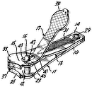
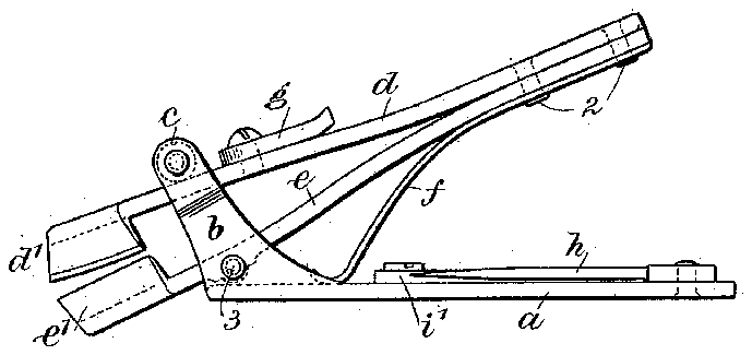
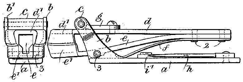
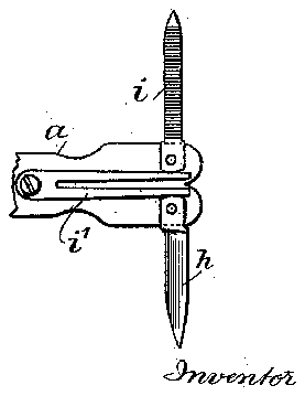
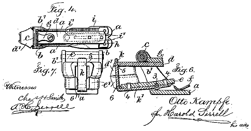
The drawings, Figure l. represents a side elevation of the device of my improvement with the aws open. Fig. 2 is a similar view with the jaws closed and held in a closed position; Fig. 3, an elevation at the cutting jaw end ofmy improved nail-clipper. Fig. Il is a plan view, in smaller size, with the jaws closed. Fig. 5 is a plan view of the baseplate alone at one end showing a knife-blade and file attachment which I prefer to employ with the device of my improvement. Fig. 6 is a vertical section at the cutting-j aw end of the clipper, showing the guiding device for centering the jaws; and Fig. 7 is an elevation at the end of the part shown in Fig. 6.
The metal base-plate a is provided at one end with upturned inclined arms b b, between the free ends of which is pivotally mounted a roller c upon its trunnion ends. Between these arms and also between the roller c and the base-plate a are spring-blades d e. These are connected at one end by the rivets 2 and I provide a spring-tongue f, secured to the union of the bent spring-blades by the same rivets 2, said spring-tongue lying against the under surface of the springblade e. These spring-blades d e are slightly bent, so that as connected there is a divergence forward of their connected ends. Their free ends are provided with the shear-cutting jaws d c, which are oppositely placed and curved in pairs. The curve of these jaws approximates the arc or curve upon which the nails should be cut, and these jaws in pairs are arranged in opposite directions for right and left hand cutting.
The lower spring-blade c is pivotally connected to the upturned arms b b" near the base-plate a by a pivot-pin 3, and as the result of the expansion of these spring-blades the upper surface of the blade d bearsupon the roller c, and when pressure is applied against the raised end of these spring-blades they are forced down from the position Fig. l into the position Fig. 2, and the blade d moves through between the inclined arms b b, the roller c revolving against the upper surface ofthe arm d, and simultaneously with this movement the pairs of cutting-jaws d e close and overlap with a shearing cut, the action being similar to the cut of a scissors. This bearing-down movement is of course against the power of the spring-tongue f, which when released is sufficient to raise the connected ends of the spring-blades d e from the position Fig. 2 to the position Fig. l, and in this movement the said blades return to an initial position separating and the jaws open ready to repeat the cut. I have shown and preferred to employ a locking-pawl g, pivotally connected to the upper surface of the blade d, and adapted when the jaws are closed, as in Fig. 2, to be turned around from the position of Fig. l to the position Figs. 2 and 4, against the roller c, so as to hold the l jaws in a closed and compact position against IOO the opening tendency of the spring-tongue f. I have shown and preferred to employ at the end of the base-plate e opposite tol the arms t b a knife-blade h and file-blade i, pivoted to the base-plate a, and an actuating-spring Q/ for holding these two members either closed or open or at the intermediate place or position shown in Fig. 5, and while these members .are advantageous to employ and are auxiliary to the operation of the nail-clipper they do not form any necessary part of my present invention.
For the purpose of relieving the shear-cutting jaws d e of strain in their operation and so as to prevent a strain in cutting the nails by one jaw comingupon the other jaw I have shown and preferred to employ a tongue 7c made integral with an arm c, the arm in turn connected by rivets 4 to the under surface of the spring-blade c adjacent to the cuttingjaws and which arm la may form part of the devices for pivotally connecting the said blade e between and to the arms b b', the tongue 7c being positioned substantially at right angles to the arm 7c and iitting within recesses 5 6, located between the pairs of cutting-j aw, said tongue in one jaw acting to guide and direct the other jaw with reference thereto, so that the strain upon the cutting edges is relieved. 1
This device is simple yet exceedingly efii-.
cient, and because of the shearing cut ofthe cutters a clean scissors-like cut is made in clipping the nails in contradistinction to the crushing severance produced ordinarily with this class of devices.
I claim as my inventionl. A nail-clipper comprising a base-plate, a pair of arms rising therefrom, a pair of springblades connected at one end and pivotally secured at an intermediate place to said arms and their free ends provided with shearcutting aws in oppositely-arranged p airs.
2. A nail-clipper comprising a base-plate, upturned arms formed therewith at one end, spring-blades secured together at one end, shear-cuttin@P jaws arranged in opposite directions at the opposite ends of said blades and spaced apart and in pairs curved to the shape of the nails for right and left hand cut.
3. A nail-clipper comprising a base-plate, upturned arms formed therewith at one end, spring-blades secured. together at one end, shear-cutting jaws arranged in opposite directions at the opposite ends of said blades and spaced apart and in pairs curved to the shape oi the nails for right and left hand cut, a pivot-pin pivotally connecting the blade nearest the base-plate to said arms, a. spring bearing upon the base-plate and connecting with the spring-blades, and means for holding the spring-blades andv their jaws in a closed position.
4. A nail-clipper comprising a base-plate, upturned inclined arms formed therewith at one end, a pivot-pin passing across through. said arms near tne base-plate and a roller pivotally mounted between the free ends of said arms, bent spring-blades riveted together at one end and coming between `said arms, the blade nearest the base-plate connected by the pivot-pin to said arms and said roller coming above the upper surface of the other blade, shear-cutting jaws formed at the end of the blades oppositev from their end connected by rivets, said jaws being spaced apart, arranged in opposite directions tor right and left hand cut and curved approximately to the shape to be given the nails, and in their movement under pressure swinging on the aforesaid pivot and moving beneath the aforesaid roller to force the jaws together to effect the cut.
5. A nail-clipper comprising a base-plate, upturned inclined arms at one end thereof, a pivot-pin passing across through said arms near the base-plate and a roller pivotally mounted between the free,ends of said arms, bent spring-blades riveted together at one end and coming between said arms, the blade nearest the base-plate connected by the pivot-pin to said arms and said roller coming above the upper surface of the other blade, shear-cutting jaws formed at the end `of the blades opposite from their end connected by rivets, said jaws being spaced apart, arranged in opposite directions for right and left hand cut and curved approximately to the shape to be given the nails, and in their movement under pressure swinging on the aforesaid pivot and moving beneath the aforesaid roller to force the jaws together to effect the cut, and a locking-pawl. pivoted to the upper spring-blade and. when the jaws are closed adapted at its free end to come against the roller to hold the parts in a closed position.
6. A nail-clipper comprising a base-plate, upturned inclined arms at one end thereof, a pivot-pin passing across through said arms near the base-plate and a roller pivotally mounted between the free ends of said arms, bent spring-blades riveted together at one end and coming between said arms, the blad e nearest the base-plate connected by the pivotpin to said arms and said roller coming above the` upper surface of the other blade,.shear-cutting jaws formed at the end of the blades opposite from their end connected. by rivets, said jaws being spaced apart, arranged in opposite directions for right and left hand' cut and curved approximately to the shape to be given the nails, and in their movement under pressure swinging on the aforesaid pivot and moving beneath the aforesaid roller to force the jaws together to effect a cut, a knife-blade and a file-blade pivotally connected to the inner face of the base-plate at one-end, and. a
spring whose free ends bear against the" IOO port occupying an inclined relation, a movable bearing formed with said inclined support and a -spring for effecting the return upturned inclined arms at one end thereof, a movement of the spring-blades, whereby the pivot-pin passing across through said arms l swinging movement of said blades on their near the base-plate and a roller pivotally i pivotal connection closes the cutting-jaws, mounted between the Ji'ree ends oi' said arms, l and effects the cut, and when released, the bent spring-blades riveted together at one spring returns the parts to an initial position. end and coming between said arms, the blade 10. ln a nail-clipper,
connected by the' a suitable support, oi a pair of spring-blades knife-blade and file-blade to hold themj closed or open.
7. A nail-clipper comprising a base-plate,
nearest the base-plate ivot-pin to said arms and said roller coming connected at one end, mounted upon said above the upper surface of the other blade, support and overlapping shear-cutting jaws shear-cutting jaws Jformed at the end of the j in oppositely-arranged pairs formed at the other and i'ree ends of said spring-blades.
blades opposite from their end connected p by rivets, said jaws being spaced apart, arj 11. lnanail-clipper, the combination with ranged in opposite directions for right and a suitable support, of a pair of spring-blades left hand cut and curved approximately to connected at one end, mounted upon said the shape to he given the nails, and in their support and overlapping shear-cutting jaws movement' under pressure swinging on the in oppositely-arranged pairs formed at the other and free ends of said spring-blades and a guiding device secured adjacent to one jaw aioresaid pivot and moving beneath the aforesaid roller to 'torce the jaws together to i and moving through an aperture ofthe other efiect the cut, and a tongue and integral arm secured to one spring-blade and passing through a recess in the other spring-blade in proximity to the shear-cutting jaws.
S. A nail-clipper comprising a base-plate, upturned inclined arms at one end thereof, a pivot-pin passing across through said arms near the base-plate and a roller pivotally mounted between the Jfree ends of said arms, bent spring-blades riveted together at one end and coming between said arms, the blade nearest the base-plate connected by the pivot-pin to said arms and said roller coming above the upper surface of the other blade, shear-cutting jaws formed at the end of the blades opposite from their end connected by j an arm device rising therefrom, a pair o spring-blades connected at one end and pivotally secured at an intermediate place to said arm device and base, and their free ends provided with normally open shear-cutting jaws in oppositely-arranged pairs.
13. A nail-clipper comprising a base-plate, an inclined arm device formed therewith at one end, spring-blades secured together at one end, and normally open shear-cutting jaws arranged in opposite directions at the opposite ends of said blades and spaced apart and in pairs curved to the shape of the nails for right and left hand cut.
rivets, sai d jaws being spaced ap art, arranged in opposite directions for right and lett hand j 14. A nail-clipper comprising spring cut and curved ap roximatelv to the shape bladessecured together at one end and norl mally open shear-cutting jaws spaced apart and arranged in opposite directions at the opends of said blades, a base-plate, an into be given the nai s, and in their movement under pressure swinging on the aforesaid ivot and moving beneath the aforesaid posite roller to force the jaws together to eiiect the j clined arm device formed therewith at one out, an arm 7c secured by rivets 4 to the und, and the base and arm device pivotally der surface ot the lowermost spring-blade l connected to the s ring-blades at an intermeand an integral tongue rising Jirom and at diate lace of the latter and in such a manner right angles to said arm and passing through that t ie arm device acts as a guide for the recesses formed between the shear-cutting movement ofthe spring-bladesjilws, said tongue forming p guide to insure l Signed by me this 11th day of April, 1906. t e accurate movement o t ie jaws.
9. ln a nail-clipper the combination with a OTTO KAM'PFE pair ot connected blades and cutting-jaws on v the free ends thereof, ci a support to which j said jaws are pivotally connected, said sup- Vitnesses:
Gno. T. PINCKNEY, JEANNETTE WniLL.
the combination with 12. A nail-clipper comprising` a base-plate,
IOO


