

- 1casing
- 2closure
- 3cap
- 4threaded shaft
- 5abrading disk
- 7cutters
- 8sha inclined edges
- 9arcuate slots
- 11nut
- 12or handle
- 13apertures
Description
PATENTED MAY 14, 1907.
M. M. RYAN. NAIL'TRIMMING DEVICE.
Show; M217 Mfg em APPLICATION FILED MAB. 1 2, 1907.
yawn:
" UNITEDSTATES PA NT OFFICE.
MARTIN M. RYAN, .oF OBEI tLIN, OHIO.
NAIL-TRIMMING DIEVICE.
der skin adjacent to the nails.
- A further object of the invention is to provide a. nail trimming tool of a rotary characterincluding cutting members whereby the nails may be' pared and an abrading disk by' may be imparted to means of which polish the trimmed edges. I
Further objects of the invention are to simplify and improve the construction and operation of this class of devices.
With these and other ends in view which will readily appear as the nature of the invention is better understood, the same'consists in the improved construction and novel arrangement and. assemblage of parts which will be. hereinafter fully described and particularly pointed out in the claims.
' In the accompanying drawings has been illustrated a simple and preferred form of the invention; it being, however, understood Specification of Letters Patent. Application filed March 12, 1907. serial No. 362.010.
that no limitation is necessarily madeto the I recise structural details therein exhibited,
ut that changes, alterations and modifica tions within'the scope of the'invention may be resorted to, when desired.
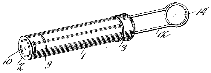
' In the drawings; Figure 1 is a perspective view of a 'nail trimming device constructed in Iaccordance with the invention. Fig. 2 is a ongitudinal sectional view of the same.
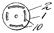
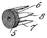
' Fig. 3 is an end view. Fig. 4 isa (perspective ing disk detached.
detail view showing the cutter an the abrad- Corresponding arts in the several figures are denoted by li e characters of reference.
The body of the'improved device-consists of a cylindrical casing 1 preferably provided with a permanent closure at one end. as shown at 2 and having at the oppos te end a detachable cap or cover 3 which may be in the nature of a screw-cap so as to bereadily detached and applied. The closure 2 and the cap 3 afford bearings for a s 'rally threaded shaft 4 which is supported or rotation in its bearings and which carries, adjacent -to and 10 throug slotted cylindrical casing,
the closure 2 an abrading disk 5, which may consist of a circular file orof a small emery wheel, securely fixed upon the shaft so as to rotate therewith. Upon the shaft 4, adja cent to the abrading disk is secured a me- I I Patented may 14, 190'}.
tallic disk'6 provided at its edge with a plu- L;
rality of cutters? cross-section so as to fitagainst the inner walls of the casing 1; said cutters being provided with sha inclined edges 8. The
- side walls. of the casing 1 and the closure 2 of,
the latterare' rovided with arcuate slots 9 which the ends of the finger nails may be inserted and held in the path of the. cutters 7 and the abrading disk 5' when said members are rotated so that the nails preferably arcutae in will be trimmed thereby, asv will be readily understood. I
Rotary motion is imparted to the spirally threaded shaft 4 and the parts carried thereby by means of a reciprocatory disk or nut 11 engaging the threaded ortion of said shaft and provided with a.y-o e' or handle 12, the
side members of which extend through apertures 13 in the cap 3; said yoke being pro vided at its outer end with an eye; 14 whereby it ma y be manipulated by the thumb of one hand to impart reci rocatory motion to the nut 11 which will t us serve to rotatethe shaft 4 within the casing, which is meanwhile bein held by or between the fingers of one hand the 'other hand are presented to the t tools through the .apertures or slots in the casing. I
From the foregoing description taken in connection withthe drawings hereunto annexed, the o eration and advantages of this invention will be readily understood. The
of the operator, while the fingernails of device isvery simple in construction, neat in appearance and efficient in o eration, and it may be readily manufacture at a moderate expense. By the use of this device, the nails may be trimmed or pared, and the. edges polished absolutely without danger of injurthe skin of the finger tips.
what l claim is:
1. In a device of the class described, 'a a shaft supported for rotation therein, and cutters sup orted upon's'aid shaftadjacent to theslotted o the casin r 2. In a evice of the class described, a
aving fully described the invention,
walls IIO cylindrical casing having slots in the side walls and ends thereof, a shaft supported for rotation in the casing and devices'mounted upon said shaft for trimming the ends of finger nails inserted through the slots or apertures.
3. In a device of the class described, a cylindrical casing having slots or apertures, a detachable cap at one end of the casing, a shaft supported for rotation in said cap and in the'opposite closed end of the cylinder or casing, and nail'trimming devices carried by said shaft adjacent to the slots and the casing.
4. In a device of the class described, aeasing, a shaft extending therethrough, nail trimming devices upon said shaft, and means for rotating the latter; said casing being provided with slots for the presentation of the ends of nails in the path of the trimming devices.
' 5. In a device of the class described, a slotted casing havin a detached cap, a spirally threaded sha t supported for rotation in the cap and in the opposite closed end of the casing, nail trimming devices carried by said shaft adjacent to the slots in the easing, a nut engaging the spirally threaded shaft, and means for reciprocating the nut to rotate the shaft.
6. In a device of the class described, a casing having a detachable cap, a spirally threaded shaft supported for rotation in the cap and in the opposite closed end of the easing, nail trimming devices carried by the shaft adjacent to the slots in the casing, a nut engaging the-spirally threaded shaft, and a yoke connected with the nut, extending through the cap and having a terminal eye.
In testimony whereof, I affix my signature in presence of two Witnesses.
' MARTIN M. RYAN. Witnesses:
KATHRYNE RYAN, LOUIS E. BURGNER.
