
- 2arm
- 7pin
- 8collar
- 10spindle
- 11spring
- 19spring
- 33line
- 66line
- 76pin
Description
PATENTED JUNE 25, 1907. :w. J. CARROLL. MANIGURE IMPLEMENT. APPLICATION FILED JUNE 25. 1906.
THE NORRIS PETERS ca, wasmucnm, n. c.
WALTER J. CARROLL, or DETROIT, MICHIGAN.
IVIANICURE IMPLEMENT.
Specification of Letters Patent.
Application filed June 25,1906. Serial No. 323,197.
Patented June 25, 1907.
To all whom, it may concern:
Be it known that I, WALTER J. CARROLL, a
' citizen of the United States, residing at Detroit, county of Wayne, State of Michigan, have invented a certain new and useful Improvement in Manicure Implements, of which the following is a specification, reference being had to the accompanying drawings, which form a part of this specification.
My invention has for its object certain new and useful improvements in a manicure implement, the same being designed more particularly to provide an instrument of this class especially adapted for cutting toe nails.
My present invention consists of the novel construction, combination and arrangement of devices hereinafter described and claimed and illustrated in the accompanying drawings, in which,
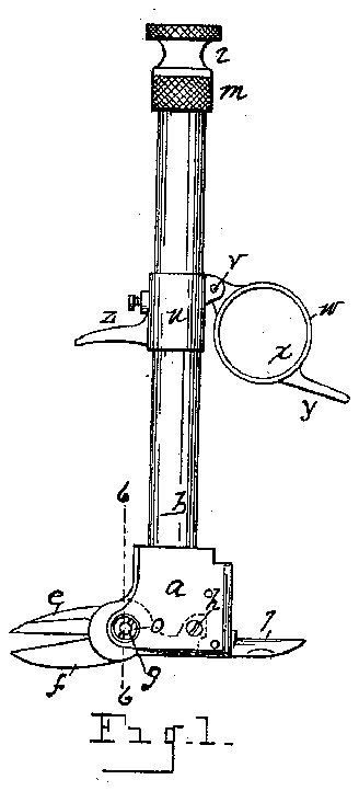
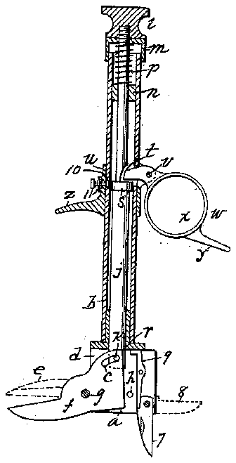
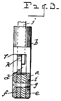
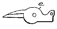
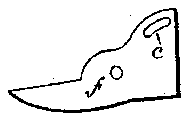
Figure 1 is a view in side elevation. Fig. 2 is a view in side elevation taken at right angles to that shown in Fig. 1. Fig. 3 is a view in vertical section on the line 33, Fig. 2, showing parts in elevation. Fig. 4 is a view of the fixed cutter blade. Fig. 5 is a view of the movable cutter blade. Fig. 6 is a view in section on the line 66, Fig. 1.
The aim of this invention is to construct an instrument for the purpose specified which will be efficient in operation and economical in its manufacture.
I carry out my invention as follows:
In the drawings 0 represents a foot or supporting member secured upon the lower end of a tubular casing b, said foot being provided on its under side with an elongated kerf or recess d in which is secured a fixed cutter blade 6 and a movable cutter blade f, the movable cutter blade being, preferably, the lower cutter blade. The movable cutter blade f is shown pivotally engaged in the foot as bya pin or screw g, the same being provided with an are shaped slot 0 at its inner and upper end, as shown in Figs. 3 and 5. The fixed cutter blade e may also be mounted upon said pin or screw g, an additional pin it being passed through its inner end to hold the blade in fixed position. I prefer that the screw 9 shall be provided with a countersunk lock nut i. It will be apparent that the cutter blades 6 and f form a pair of shears. The cutter blades are preferably .constructed with straight cutting edges. A plunger or'push rod jis made reciprocatory in the tubular casing 1), said push rod being engaged with the movable cutter blade as by a pin 7.? engaged in the slot 0. Upon the upper end of the push rod is a cap Z, a collar m beneath the head being shown sleeved upon the upper end of the casing, and having a limited reciprocation thereupon. Within the upper end of the casing I also locate a bushing n engaged upon the push rod, a spring 19 resting upon one end thereof, said spring engaged to exert its tension upon the push rod to hold it in normal position, i. 6., in position to open the movable cutter blade. The lower end of the push rod is preferably formed with a shoulder r, as shown in Fig. 6, so that the adjacent upper edge .of the movable cutter blade will bear upon said shoulder. This arrangement will, obviously, relieve the strain upon the movable cutter blade from the pin 76, the strain being upon said shoulder in operation. The push rod is further provided with a collar s, the push rod being also recessed preferably above the collar 8 as indicated at t. Upon the exterior of the casing I) is engaged a sleeve it upon which is fulcrumed as at c an operating lever w preferably constructed with a ring 00 to receive a finger of the operator, and with a protecting lever arm y under which another finger of the operator may be engaged. The sleeve is also provided with a fixed arm 2 under which still another finger of the operator may be engaged.
It will be evident that the cutting away of the push rod as at 13 forms a shoulder therebeneath upon which the inner end of the lever to is engaged. It will also be obvious that the operator, grasping the lever w and arms y and 2, the palm of the hand resting upon the head or cap Z, by the act of closing his fingers toward the palm, will lift the outer end of the lever w thereby depressing the plunger which,
in turn, bearing upon the heel of the movable cutter blade, will actuate said blade closing its cutting edge against the cutting edge of the fixed blade. By releasing pressure upon the lever w, the spring 1) restores the plunger and the movable cutter blade to normal position.
In the slot or recess (Z of the foot a I also fulcrum a knife blade'indicated at 7 and a file blade 8. Springs 9 exert their tension upon said blades in a customary manner.
It will be seen that the lever to is so shaped that it may readily be grasped by the second and third fingers of the hand, while the arm 2 may be engaged'by the first finger.
To hold the movable blade in closed posiextending to the exterior of the case b, the inner end normally bearing against the collar 8. A spring 11 holds said spindle normally disengaged from said collar. It will be evi dent that when the plunger is depressed, the spindle 1.0 may be forced inward over the collar 8 to hold the plunger from retraction, when it is desired to operate the device by a downward movement of the plunger, the spindle 10 will be restored to normal position.
What 1 claim as my invention is:
1. An implement embodying a supporting member, a tubular casing engaged with said member, a fixed cutter blade secured to said member, an oscillatory cutter blade lulcrumed to said member, a push rod reciprocatory within the casing engaged with the oscillatory cutter blade, and a lever to actuate the push rod.
2. An implement embodying a supporting member, a tubular casing engaged with said member, a fixed cutter blade secured to said member, an oscillatory cutter blade fulcrumed to said member, a push rod reciprocatory within said casing engaged with the oscillatory cutter blade, and a lever to actuate the push rod, said oscillatory cutter blade constructed with an are shaped slot at the inner end thereof, and the push rod provided with a pin engaged in said slot.
3. An implement embodying a supporting member, a tubular casing engaged with said member, a fixed cutter blade secured to said member, an oscillatory cutter blade fulcrumed to said member, a push rod reciprocatory within said casing engaged with the oscillatory cutter blade, and a lever to actuate the push rod, said oscillatory cutter blade constructed with an are shaped slot at the inner end thereof and the push rod provided with a pin engaged in said slot, said push rod cut away toward its lower end forming a shoulder above said pin, the strain of the oscillatory cutter blade being communicated to said shoulder.
4. An implement embodying a slotted supporting member, a fixed and an oscillatory cutter blade secured within the slot of said supporting member, a tubular casing engaged with said member, a push rod reciprocatory within the casing to actuate the oscillatory cutter blade, and a lever supported upon the casing to actuate said push rod.
5. An implement embodying a supporting member, a fixed and an oscillatory cutter blade engaged with said member, a tubular casing engaged with said member, a push rod reciprocatory within the casing to actuate the oscillatory cutter blade, a sleeve upon the casing, and a lever fulcrumed upon said sleeve to actuate the push rod.
6. An implement embodying a supporting member, a fixed and an oscillatory cutter blade engaged with said member, a tubular casing engaged with said member, a push rod reciprocatory within the casing to actuate the oscillatory cutter blade, a sleeve upon the casing, and a lever lulcrunied upon said sleeve to actuate the push rod, said sleeve provided with a fixed laterally projecting arm.
7. An implement embodying a supporting member, a fixed cutter blade secured thereupon, an oscillatory cutter blade lulcrumed upon said member, a reciprocatory push rod engaged with the oscillatory cutter blade, a lever to actuate the push rod, and means to lock the push rod to hold the oscillatory cutter blade'in closed position.
8. An implement embodying a slotted supporting member, a fixed and an oscillatory cutter blade secured within the slot 0] said member, a tubular casing engaged with said member, a self retracting push rod reciprocatory within the casing to actuate the oscillatory cutter blade, a sleeve upon the casing, and a lever supported upon the casing, the inner end of the lever projecting through the casing and engaging the push rod.
9. An implement embodying a supporting member, a tubular casing connected therewith, a fixed cutter blade secured upon said member, an oscillatory cutter blade iulcrumed upon said member, and means reciprocatory within the casing to actuate said oscillatory cutter blade.
10. An implement embodying a slotted supporting member, a tubular case engaged therewith, a fixed cutter blade secured within the slot of said member, an oscillatory cutter blade fulcrumed within said slot, and a push rod within said tube or case to actuate said oscillatory cutter blade.
11. An implement embodying a slotted supporting member, a tube or case engaged therewith, a fixed cutter blade secured within the slot of said member, an oscillatory cutter blade fulcrumed within the slotted member, and a push-rod within said tube or case to actuate said oscillatory cutter blade, said push bar having a limited upward and downward movement, and means to lock the oscillatory blade in closed position.
12. An implement embodying a supporting member slotted at its lower end, a fixed cutter blade secured ithin the slotted member, an oscillatory cutter blade lulcrumed within said member, a tube or case engaged with said member, a reciprocatory push rod within said tube or case, and means secured upon said tube or case to actuate said push rod.
In testimony whereof, I have signed this specification in the presence of two subscribing witnesses.
YVALTER J. CARROLL.
Witnesses JAMES F. HILL, N. S. inear.
