

- 1claimed
- 3laterally extending stop lug
- 5shearing member
- 6shearing member
- 7pivot pin or screw
- 8flanges
- 9co-acting cutting edges
- 11arms
- 12knife
- 13cutting edges
- 14point
- 15locking member or plate
- 16elongated slot
- 18slot
- 20pin
- 22knob or finger piece
- 23file
- 24shearing member 6 bya rivet
- 25locking screw
- 28recess or chamber
- 29perforation
- 31guiding lug
- 32wall
- 33end wall
Description
PATENTED JULY 9, 1907.
E.- H. STODDARD. MANIGURE IMPLEMENT. APPLICATION FILED JALLZI, 1907.
A TTOR/VEVS Tut NORRIS FITIRS co.. wulnnc'mu, D.
ERNEST H. STODDARD, OF ORANGE, MASSACHUSETTS.
MANIGURE IMPLEMENT.
Specification of Letters Patent.
Patented July 9, 1907.
Application filed January 21, 1907. S a NO- 353,334.
To all whom it may concern:
Be it known that I, ERNEST H. SrroDnARn, a citizen of the United States, residing at Orange, in the county of Franklin and State of Massachusetts, have invented .a new and useful Manicure Implement, of which the following is a specification.
This invention relates to manicure implements and has for its object to provide a comparatively simple and inexpensive device of this character especially designed for trimming and manicuring the finger nails and which may be conveniently folded and carried in the pocket.
A further object of the invention is to provide a manicure implement including a pair of shears the cutting edges of which terminate in inwardly extending arms constituting tweezers, said shears having combined therewith a file, knife and piercing point or needle.
A further object is to provide a longitudinally movable guard for protecting the cutting edge of the knife when the instrument is carried in the pocket, said guard also serving to lock the pivoted legs of the shears in closed or inoperativeposition.
A still further object of the invention is to generally improve this class of devices so as to increase their utility, durability and efficiency as well as to reduce'the cost of manufacture.
Further objects and advantages will appear in the following description, it being understood that various changes in form, proportions and minor details of con- "striic'tion may be resorted to within the scope of the appended claims.
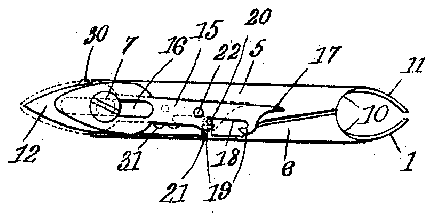
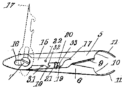
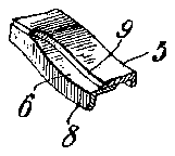
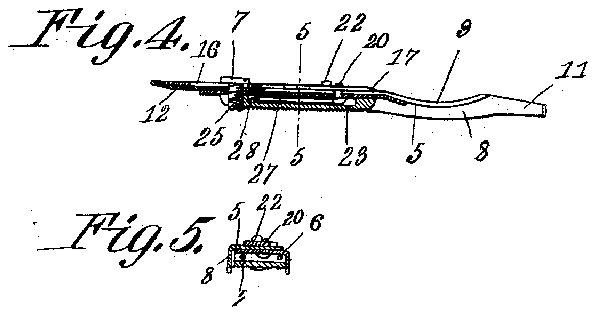
In the accompanying drawings forming a part of this specification: Figure 1 is a top plan view of a manicure implement constructed in accordance with my invention showing the several parts in locked or assembled position. Fig. 2 is a similar view showing the locking member released and showing in dotted lines the piercing point or needle moved laterally to operative position. Fig. 3 is a bottom plan view of Fig. 1. Fig. 4 is a longitudinal sectional view takenon the line 4-4 of Fig. 3. Fig. 5 is a transverse sectional view taken on the line 5-5 of Fig. 4. Fig. 6 is a perspective view partly in section of one end of the implement showing the concaved upper surface of the shearing members.
Similar numerals of reference indicate corresponding parts in all of the figures of the. drawings.
The improved device consists of a pair of shearing members or legs 5 and 6 having their inner longitudinal edges over-lapped and pivotally united by ascrew or similar fastening device 7 andhaving their outer edges provided with longitudinal reinforcing flanges 8 so. that the shearing members may be convenientlygrasped in the hand when operating the same. 7
The upper surfaces of the shearing members 5 and G are preferably concaved, as shown and provided with co-acting cutting edges 9, the'metal' at said cutting edges being cut away, as indicated at 10 and the reinforcing flanges 8 of said members bent laterally to form inwardly extending arms 11 constituting tweezers.
One end of the shearing member 5 is extended beyond the adjacent end of the mating member to form a knife 12, the cutting edges 13 of which are preferably inclined towards one end of the iinplement to form a terminal point 14 which may be used for removing dirt and other foreign matter from beneath the finger nails.
As a means for locking the shearing members 5 and G in closed or inoperative position there is provided a longitudinally movable locking member 15 preferably in the form of a flat plate having an elongated slot 16 formed therein for thereception of the pivot pin or screw '7 and having its slotted end curved to conform to the general contour of the knife 12, the opposite end of said plate or looking member being reduced to form a piercing point or needle 17 designed to extract slivers from the skin or for removing black-heads, or puncturing pimples and for other purposes.
The reduced end of the locking member or plate 15 is provided with an elongated slot 18 opening through one side of the plate and defining spaced longitudinally disposed locking lips 19 adapted to engage a locking pin 20 secured to or formed integral with the shearing member 6, there being a transverse recess 21 formed in the shearing member 5 for the reception of the pin 20, as shown.
The locking member 15 is preferably provided with a knob or finger piece 22 by means of which the locking member may be conveniently moved to operative and inoperative position.
Seated between the flanges 8 and preferably disposed at the pivotal juncture of the shearing members 5 and 6 is a reinforcing plate 23 having its exposed surface roughened to form a file, said plate'being rigidly secured to the shearing member 6 bya rivet 24 and the locking screw25.
- The locking screw 25 bears againstthe adjacent end of the pivot pin or screw 7 and thereby locks said pivot pin or screw 7 against accidental rotation on the shearing members.
The shearing members-5 and 6 are normally and A yieldably supported inopen or operative positionby means of a-spring 27 one end of which bears against the flange 8 of the shearing member 6 while the opposite end thereof extends through a recess or chamber 28 formed in the file 23 and is seated in a perforation 29 formed in the flange 8 of the shearing member 5.
' Attention is called to the fact that one end of the shearing member 5 is extended longitudinally beyond the plate or file 23 and is provided with a laterally extending stop lug 3 which by engagement with the flange 8 on the shearing member 5 serves .to limit the. lateral movement of said shearing member. It will inoperative position.
also be observed that the pin 20 by engagement with the wall of the slot 21 serves to limit the inward movement of the shearing members and thus prevents the terminals of the tweezers from coming in contact with each other when the shears are in closed position.
A guiding lug 31 is secured to or formed integral with the upper surface of the shearing member'5 and serves to guide the locking member or plate 15 when the latter is moved to operative and inoperative position.
In operation when it is desired to use the knife 12 for cleaning the nails or for any other purpose the locking member or guard 15 is moved longitudinally of the shearing members until the pin 20 engages the wall 32 of the slot 18 and in which position the knife may be conveniently used while the shearing members are in locked position.
In order to use the shears it is merely necessary to adjust the locking plate 15 longitudinally of the shears until the opening 18 registers with the pin 20 when the spring 27 will force the shearing members apart and thus permit the same to be used by exerting a lateral pressure on the flanges 8.
The piercing member or point may be used by moving the same to the dotted line position shown in Fig. 2 of the drawings or by further rotating the same until the point 17 is in alinement with the point 14 of the knife 12.
In order to lock the several parts in closed or inoperative position it is merely necessary to slide the plate 15 longitudinally of the shearing members until the end wall 33 of the slot 18 bears against the pin 20 and in which position the guard covers the cutting edges of the knife 12 and the adjacent lip 19 by engagement with the pin 20 looks the shearing members against lateral movement.
It will b noted that the adjacent ends of the arms 11 constituting the tweezers are normally spaced apart so that said tweezers may be employed for removing hairs and the like fromthe skin without the necessity of first releasing the locking member.
From the foregoing description it will be seen that there is provided an extremely simple, inexpensive and efficient device admirably adapted for the attainment of the ends in View.
Having thus described the invention what is claimed 1. A manicure implement including shearing members, a knife carried by one of the shearing members, and
means forming a guard for the cutting edge of the knife and serving to lock the shearing members in inoperative position.
2. A manicure implement including shearing members one of which terminates in a knife, and means forming a guard for the cutting edge of the knife and serving to lock the shearing members in inoperative position, said locking means being provided with a piercing point.
3. A manicure implement including pivotally united shearing members, the ends of which constitute tweezers, a knife carried by one of the'shearing members, and means forming a guard for the knife and serving to lock the shearing members in inoperative position.
4. A manicure implement including pivotally united shearing members having longitudinal reinforcing flanges terminating in inwardly extending arms constituting tweezers, and means for locking the shearing members in 5. A manicure implement including pivotally united shearing members the upper surfaces of which are concaved at the cutting edges thereof, a knife carried by one of the shearing members and means forming a guard for the knife and serving to lock the shearing members in inoperative position.
6. A manicure implement including pivotally united shearing membersv one of which terminates in a knife, a locking pin carried by the opposite member, and a guard slidably mounted on the knife carrying member and adapted to engage the pin for locking the shearing members in inoperative position.
7. A manicure implement including pivotally united shearing members having longitudinally disposed reinforcing flanges, one of said members being provided with a ing adapted to engage the reinforcing flange of the opposite member for limiting the lateral movement of said shearing members, a spring for yieldably supporting the shearing members in operative position, and means for locking said shearing members in inoperative position.
8. A manicure implement including pivotally united spring pressed shearing members one of which terminates in a knife, a plate slidably mounted on one of the shearing members and constituting a guard for the knife, and means carried by the plate and adapted to engage the opposite shearing member for locking said shearing members in inoperative position.
9. A manicure implement including pivotally' united shearing members one of which terminates in a knife, a
plate slidably mounted on the knife carrying member and provided with an elongated slot for the reception of the pivotal pin "or said shearing members, said plate being provided with a terminal piercing point.
10. A manicure implement including pivotally united shearing members provided with longitudinal reinforcing flanges, a file disposed at the pivotal juncture of the shearing members and seated between the flanges, and a locking member slidably mounted on one of said members and adapted to engage the opposite member for locking said members in closed position.
11. A manicure implement including pivotally united shearing members, a pin forming the pivotal connection between said members, a file carried by one of the members, and a locking screw extending through the file and engaging the pivotal pin.
12. A manicure implement including pivotally united shearing members, a pin forming the pivotal connection between the two, a plate secured to one of the members and having its upper surface constituting a file, said plate being provided with a recess, a spring seated insaid recess and bearing against the shearing members for yieldably supporting the same in open position, means for locking the shears in closed position, and a locking screw extending through the plate and bearing against the pivot pin.
13. A manicure implement including pivotally united shearing members provided with longitudinal reinforcing flanges having their ends cut away at the shearing edges thereof and bent laterally to form inwardly extending arms constituting tweezers, a "knife carried by one of the shearing members, a pin carried by the other shearing member, and a locking member slidably mounted'on the knife carrying member and constituting a guard for said knife, said locking member being provided with locking lips adapted to engage the pin for locking the shearing members in closed position.
.14. A manicure implement including pivotally united shearing members one of which is provided with a knife, :1 plate slidably mounted on the knife carrying member and having a slot formed therein for the reception of the pivot pin of said members, locking lips carried by one end of the plate, a pin carried by the adjacent shearing member and adapted to engage the lips for locking said shearing members in closed position, said plate having one end thereof reduced to form a piercing point and provided with a finger piece for moving the plate to operative and inoperative position.
15. A manicure implement including pivotally united shearing members one of which is provided with a laterally extending pin and the other with an inwardly extending recess adapted'to receive the pin when'the locking members are moved to closed position, and a plate provided with a longitudinal slot opening through one,
edge of the plate and defining locking lips adapted to engage the pin for locking the shearing members in closed position.
16. A manicure implement including pivotally united shearing members having longitudinal reinforcing flanges, one of said shearing members being provided with a knife and the other with a stop lug adapted to engage the flange of the knife carrying shear member, a locking plate slidably mounted on the knife carrying member and constituting a guard for the cutting edge of said knife, a pin secured to one of said members, a locking lip carried by the plate and adapted to engage the pin for locking the shearing members in closed position, means for guiding the plate, and a finger piece carried by said plate for moving the same to operative and inoperative position.
In testimony that I claim the foregoing as my own, I have hereto affixed my signature in the presence of two Witnesses.
M. JOSEPHINE FOWLER, EDWARD C. FOWLER.