- 1body
- 2seat
- 3perforation
- 4form two bearings
- 5slot
- 7sides
- 8blade
- 10rib
- 11screw
- 12portions
- 13arms
- 14hook
- 15operating lever
- 17projection
- 18arms
- 19nail cleaner
- 20perforation
- 21notch
Description
WITNESSES:
PATENTED JULY 23, 1907.
G. HAVELL. NAIL CLIPPER.
APPLICATION FILED NOV. 28,1906.
IQ @W 1n: uoxms PETlRs cm, WASNINGION, n. c.
UNITED STATES PATENT OFFICE.
GEORGE HAVELL, OF NEWARK, NEW JERSEY, ASSIGNOR TO LOUIS o. LANGIE, OF
ROCHESTER, NEW YORK.
NAIL-CLIPPER.
Specification of Letters Patent.
Patented July 23, 1907.
Application filed November 28, 1906. Serial No. 345,567.
To all whom it may concern:
Be it known that I, GEORGE HAVELL, a citizen of the United States, and a resident of Newark, in the county of Essex and State of New Jersey, have invented certain new and useful Improvements in Nail-Clippers, of which the following is a specification.
This invention relates to nail clippers, and consists in the mechanism hereinafter described and claimed.
The object of the invention is to produce a nail clipper of few parts, easily manufactured, and easily assembled.
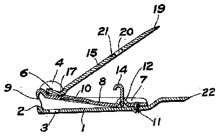
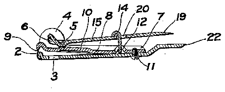
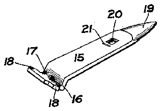
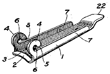
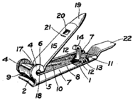
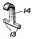
In the drawings'. Figure l is a vertical section through the middle of a nail clipper embodying this invention, and showing the parts in the open position; Fig. 2 is a similar vertical section, showing the parts in a locked position; Fig. 3 is a perspective view of the operating lever of the nail clipper; Fig. 4 is a perspective view of the main frame piece of said nail clipper; Fig. 5 is a perspective view of the complete nail. clipper (part being broken away), with the parts in the same position shown in Fig. 1; and Fig. 6 is a perspective view of the lock or latch.
The nail clipper has a body 1, as shown in Fig. 4, composed of one piece, and having at its front end a seat 2 composing one of the jaws of the cutting device, and adjacent to said jaw a perforation 3, seen most clearly in Figs. 1 and 2. Adjacent to the seat 2, the sides 7, 7 of the body piece 1 are turned up to form two bearings 4 for the operating lever. Each bearing has an entrance slot 5, above which, at the inner end, is a lateral slot 6 constituting an extension of the slot 5. The sides 7 of the body 1 may be turned up, through a greater or smaller portion of the length thereof, to form a box to contain the cutting blade 8. This cutting blade, at the front end, has the knife edge 9 adapted to cooperate with the seat 2. On the back of the blade 8 is a rib 10. At the rear end the blade is fastened to the body 1 by suitable means, such as the screw 11,
and at a suitable point the blade is perforated, and has two raised portions 12 adjacent to the last mentioned perforation. Under these raised or arched portions 12 rest the arms 13 of a hook 1 1, which turns upon said arms as upon pivots.
The blade 8 and body 1 are assembled by placing the arms 13 in position under the arches 12, and then fastening the blade 8 to the body 1 by means of the screw 11. The operating lever 15 has a sharp curve 16 at one end, and in the center of said curve is a notch or depression adapted to fit the rib 10 of the blade 8. This notch or depression is indicated in Fig. 3 by the projection 17. Closer to the end of the lever than the bend 16 are two lateral arms 18, which constitute the pivots upon which the operating lever turns.
When the blade 8 is pressed down tightly upon its seat 2, the arms 18 may be slipped through the slots 5,
and then upon releasing the blade 8, which is of spring metal, the arms 18 are forced up into the lateral slots 6 and are maintained in that position, as shown in Figs. 1. and 5. On depressing the free end of the lever 15, the blade 8 is bent so that the knife blade 9 may press with suflicient force against the seat 2. The lever 15 at its free end is shaped to form a nail cleaner 19, and through the said operating lever is a perforation 20, adjacent to which may be a notch 21. The perforation 20 is in such a position that when the hook 14 stands upright, as shown in Figs. 1, 2 and 5, and the operating lever 15 is swung downward, the said hook passes through the perforation 20, and, on being moved forward slightly, the edge of the hook engages in the notch 21. The spring action of the blade 8 will retain the parts in the closed and locked position shown in Fig. 2.
The free end of the body 1 may be. extended, as at 22, to be used for pressing backward the thin skin at the bases of the nails.
The under surface of the operating lever 15 may be cut as a file.
What I claim is:
1. The combination in a nail clipper, of a body provided with a jaw and with two bearings, each bearing having an entrance slot and a lateral extension therefrom, an operating lever having arms resting in said extensions, and a spring actuated by said operating lever and carrying a cutter to cooperate with said jaw, the said spring also pressing on said operating lever and retaining said arms in said lateral extensions.
2. A nail clipper composed of a body provided with a jaw and with two bearings, each bearing having an entrance slot and a lateral extension therefrom, an op erating lever having arms resting in said extensions, and a spring jaw fastened to said body and actuated by said operating lever and pressing on said lever and retaining said arms in said lateral extensions.
3. The combination in a nail clipper, of a body, an operating lever pivoted in said body, a spring cutter actuated by said lever and fastened to said body and having a perforation and arched portions adjacent to said perforation, and a catch for engaging the operating lever projecting through said perforation and having arms held in said arched portions by said body.
4. A nail clipper composed of a body, an operating lever pivoted in said body, a spring cutter actuated by said lever and fastened to said body and having arched portions, and a catch for engaging the operating lever having arms held in said arched portions by said body.
5. The combination in a nail clipper, of a body provided with a jaw and with two bearings, each bearing having an entrance slot and a lateral extension therefrom, an operating lever having a depression and having arms resting in said extensions, and a spring actuated by said operating lever and carrying a cutter to cooperate with said jaw and having a rib to rest in said depression, the said spring also pressing on said operating lever and retaining said arms in said lateral extensions.
GEORGE HAVELL. Witnesses:
J. D. CLARK,
A. G. \VILLIAMS.


