
- 1body
- 2jaw
- 7tail
- 8lever
- 10spring
- 12pivot pin
- 13file
- 16opening
- 17prong
- 111ears
Description
IH.`D.BADER.
COMBINED NAIL GLIPPER AND PILE. APPLIOATION FILED 1111.2, 1910.
Snag
MISES@ Y inventor:
0U. .1562 H. Dadar bY ZEW/1th??- Patented Aug. 16,1910.
. movable relative to the other,
is a side elevation of the clipper nUniTin) sTATEs PATENT OFFICE.
HERBERT D. BADER, OF ST. LOUIS, MISSOURL ASSIGNOR TO SIMMONS HARDWARE COMPANY, OF ST. LOUIS, MISSOURI, A. CORPORATION.
COMBINED NAIL CLIPPER AND FILE.
Specication of Letters Patent.` Patented Aug', 16, 1910.
Application led February 2, 1910. Serial No. 541,607.
To all whom it may concern;
Be it known that I, HERBERT a citizen of the United States of America, residing in the city of St. Louis and State of Missouri, have invented certain new and useful Improvements in Combined Nail Clippers and Files, of whichv the following is a full, clear, and exact description, reference being had to the accompanying drawings, forming part of this specification.
My invention relates to that character of nail clippers in which there are two jaws having cutting edges and one of which is and a lever for operating the movable jaw, the clipper having associated with it a nail iile that is pivoted to the clipper and is adapted to be folded thereagainst when not in use and to be `unfolded for use. The nail files asso ciated with clippers of this kind are loosely connected to members of the clippers and when they areunfolded and used, there is absence of means for holding them in the unfolded position, and it is necessary to offer resistance in the use of the file to prevent its movement away from the nail being operated upon, the usual manner of affording this resistance being that of placing the finger of the user against the back of the le. This, however, is unsatisfactory, for the reason that the finger does not give a firm support for the file and is, therefore, permitted to yield baclrwardly while in use, with the result of unsatisfactory filing action.
The object of my invention is to provide means embodied in the clipper and le whereby the file may be firmly held while it is unfolded. b
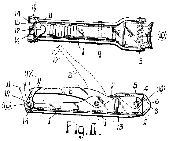
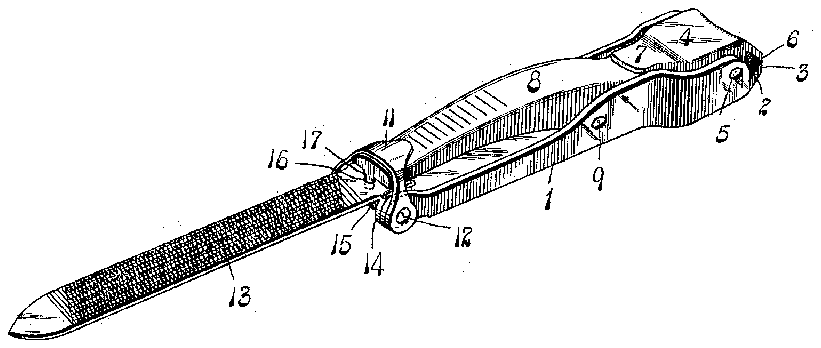
Figure I isa top or plan view of a nail clipper and file having my improvement embodied therein with the lile folded. Fig. II file with the file folded. Fig. III is an enlarged perspective view of the tile unfolded.
In the accompanying drawings :-1 nates the body of my nail clipper, at the forward end of which is a jaw 2 that is provided with a cutter 3.
4: is a movable jaw pivoted to the jaw 2 at 5 and which is provided with a cutting edge G that is movable to and from the cutting edge of the other jaw.
8 is a lever pivoted intermediate of its ends at 9 to the body 1 and the forward arm of which is located beneath the tail 7 D. BADER,
desigproviding for the acto carry its cutting of the jaw Ll, thereby tuation ofthe jaw 4 edge 3.
Reverse `movement of the movable jaw l is obtained by the employment of a spring 10 that is situated between the jaws 2 and 4 and is preferably arranged around the pivot pin at 5 and has arms that rest against the jaws. n j
11 is a latch "yoke that is movably connected to the rear end of the body 1 by a pivot pin 12 and is adapted to occupy a osition over the free end of the lever 8 to holdthe lever depressed when it is not in use, but which may be swung into the position seen in dotted lines, Fig. II, to free the lever when the clipper is to be used.
`13 designates a nail lile provided with ears 111 by which the file is pivotally` connected to the pivot pin 12 in order that it may be folded into the position seen in Fig. II and extended into the unfolded position seen in Fig. III.
15 is a spring located at the point of piv otal mounting of the file and by which said file is moved to the folded position and retained in such position when not in use.
The nail clipper and file made as thus far specifically described is known to be old and no invention per se is herein claimed for the parts enumerated.
In the rear or heel end-of the file 13 is an opening 16 and extending from the rear end of the lever 8 is a prong 17 that is adapted to enter into said opening when the file is swung into the unfolded or extended posi tion seen in Fig. III, and by reason of virtual entrance, the file is firmly held in its extended position due to the engagement between the lever and the file preventing the turning of the file upon its pivot. After the prong 17 has been introduced into the opening in the file, the latch 11 is swung into position over the free end of the lever and acts to maintain the connection between the lever and the file to firmly hold the le at the same time that it holds the lever in its depressed position, and the ile may, therefore, be utilized with a high degree of satis faction due to its being held from movement a movable member pivoted to saidi movablel memberis adapted to be said body, and means for connecting said movable member to said le when the file is ink an extended position, whereby the file is held from turning'on its pivot in either direction.
2. A combined nail clipper and file, comprising a clipper body, a le pivoted to said clipper body, a movable member pivoted to saidl body, means for engagement between said movable member and said iile when the ile is in. an extended position, and a latch with an opening adapted to receive said prong to hold the file from movement relative to the movable member.
5. A combined nail clipper and file, comprising a clipper body, a movable member carried by said clipper body, a lile pivoted to said clipper body and toward which said movable member is moved when the file is inan extended position; one of said members being provided with an opening, the other member beingy provided with a )rong entering into said opening to provi e engagement of such parts, and a latch pivoted to saidl body engaging said movable member to maintain the engagement between it and the file.
6. A combined nail clipper and file, comprising a clipper body, a movable member carried bysaid clipper body, a file pivoted to said clipperl body and toward which said movable member is moved when the file is in an extended position; said movable member being provided with a prong, and said lile being provided With an opening receiving said prong, and a latch pivoted to said body engaging said movable member to maintain the engagement between it and the file.
for maintainingV the engagement specied.
3. A combined nail clipper and iile, comprising a clipper body, a movable member carried by saidl clipper body, a le member pivotedL to saidclipper body and adapted to be swung into an extendedl position .andL toward which said movable member is adapted to be moved when the le is in an extended position; one of said members being provided with an opening and the other member being provided With a prong adapted to enter said openingto hold the file from movement; relative to the clipper body.
4. A combined nail clipper and file, comprising av clipperk body, a movable member carried by said clipper body, a lile pivoted to saidclipper body and adaptedto be swung intoanextended position. and towardV which HERBERT D BADER.
In the presence of* JOSEPH A. MCNAMARA, EDWARD H. JAEGER.
moved when the file is in an extended position.; said movable member beingv provided with a prong, and said file being provided


