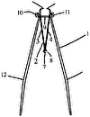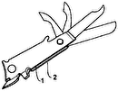
- 7free end
- 9lug
- 10nail clipper
- 11jaws
- 13pivot pin
- 14inturned flanges
- 16longitudinal slot or notch
- 17flanges
- 18pivot pin
- 19fingers
- 21rivet or similar fastening
- 22ith transverse beads or grooved portions
- 66line
Description
J. A. BROWNING.
NAIL CLIPPER.
APPLICATION FILED APB..16, 1910.
994, 1 1 9. Patented June 6, 1911.
Z0 HI 0 JAB. Z2
' wmm z wiltwamo W to JUSTUS A. BROWNING, OF OGDEN, UTAH.
NAIL-CLIPPER.
Specification of Letters Patent.
Patented June 6, 1911.
Application filed April 16, 1910. Serial No. 555,825.
To all whom it may concern.-
Be it known that I, JUs'rUs A. BROWNING, a citizen of the United States, residing at Ogden, in the county of Weber and State of Utah, have invented a new and useful Nail- Clipper, of which the following is a specification.
This invention relates to nail clippers, and has for its object to provide an improved device of this class so as to enable the same to fold fiat against the shank by which it is carried and be retained in its closed position by the resiliency of the spring members of the clipper.
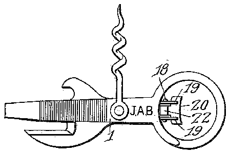
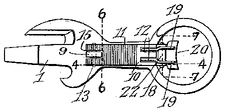
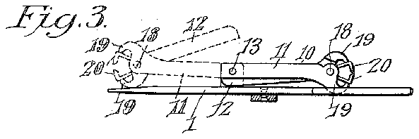
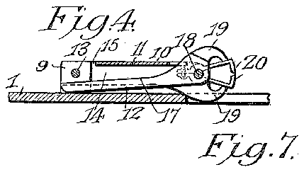
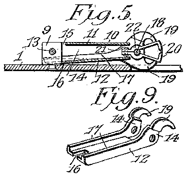
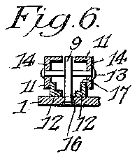
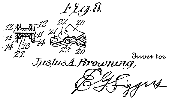
In the annexed drawings, which fully illustrate the invention, Figure 1 is a plan view of the tool, Fig. 2 is a reverse plan view of the same. Fig. 3 is an edge view. Fig. 4 is a longitudinal section on the line 4-4 of Fig. 2. Fig. 5 is a central longitudinal section. Fig. 6 is a detail sectional view on the line 66 of Fig. 2. Fig. 7 is a detail sectional view on the line 7-7 of Fig. 2. Fig. 8 is a detail perspective view of the spring-members of the nail clipper. Fig. 9 is a detail perspective view of one jaw of the clipper.
Referring to the drawing, the shank or body 1 is provided with a lug 9, to which the nail clipper 10 is pivotally secured. This nail clipper 10 consists of a pair of jaws 11 and 12 which are pivotally connected near their outer ends, and one of which, 11, is pivoted to the lug 9 by a transverse pivot pin 13, as shown. The said jaw is provided with inturned flanges 14 at its edges through which the said pivot pin passes, and it is also provided with a longitudinal slot or notch indicated at 15 to accommodate the said lug 9. The coacting jaw 12 is likewise provided with a longitudinal slot or notch 16 at its free end, which is adapted to engage the lug 9, and this jaw is likewise provided with flanges 17 at its edges adapted to fit between the flanges of the jaw 11, as shown in Fig. 7. These flanges serve to reinforce the jaws and also provide means for the mounting of a pivot pin 18 by means of which the jaws are pivoted together near their outer ends. The jaws cross each other at their points of pivotal engagement with the pin 18, and the side flanges of the jaws are extended beyond the ends of the main portions of the jaws so as to provide curved fingers 19 which are arranged to project toward each other, as shown clearly in Figs.
4 and 5, and bear upon the resilient clipping plates 20 which are secured together at their inner ends by a rivet or similar fastening 21 and are provided intermediate their ends with transverse beads or grooved portions 22 adapted to fit loosely around the pivot pin 18, as will be readily understood. The outer free ends of these resilient clipping members are extended laterally so as to fit be tween and be engaged by the fingers 19 of the jaws 11 and 12, so that when the inner ends of the jaws are pressed together, the fingers will be caused to approach and force the clipping edges of the said resilient men1- bers together so as to clip a finger nail placed between them.
When the tool is not in use, it may be carried in the pocket and the nail clipper will lie against the shank, as shown in Fig. 3. In this position of the parts, the free end of the jaw 12 of the nail clipper will bear against the side of the shank between the same and the pivot pin 13 and owing to the resiliency of the clipping members 20 and the location of the pivot pin, the pressure of the free end of the jaw against the shank will hold the clipper in its closed position, inasmuch as the tendency of the clipping members is to normally separate and consequently force the ends of the jaws 11 and 12 apart. This tendency is resisted by the free end of the jaw 12 being thrown against the side of the shank 1, and, as the end of the jaw will be beyond the pivotal point of connection between the nail clipper and the shank, the accidental movement of the clipper away from the shank will be prevented. When it is desired to use the nail clipper, the outer end of the same is easily swung away from the side of the shank by a slight pressure thereon and the jaws will then be caused to assume the relative positions indicated in dotted lines in Fig. 3. It will thus be seen that the same spring which serves to hold the jaws of the clipper normally separated and to clip the nails, also serves the function of holding the jaws locked against the side of the shank when it is not in use.
From the foregoing description, taken in connection with the accompanying drawings, the advantages of the construction and of the method of operation will be readily apparent to those skilled in the art to which the invention appertains, and while I have described the principle of operation of the of said jaws being pivotally attached to the side of the shank and the other jaw having a free end adapted to lie against the shank between the same and the pivotal connection of the first-mentioned jaw thereto, and a s rin cli Jin member mounted between the jaws and acting on the said free jaw so as to cause a frictional engagement between the end of the same and the side of the shank.
2. The combination of a shank having a lug projecting from one side, and a nail clipper having a member pivotally attached to the said lug, a second member pivotally attached to the first member near the outer end of the same and having a free end 7 adapted to lie against the side of the shank between the same and the pivot of the firstmentioned member, the ends of the members being opposed beyond the pivotal connection of the same, and a spring clipping member loosely mounted between the said jaws around the pivotal connection of the same and acting on the outer ends of the same to throw them normally apart.
3. The combination of a shank having a lug projecting from one side, and a nail clipper comprising a member having one end pivoted to the said lug, a second member pivoted to the first-mentioned member near the outer end of the same and having a free end provided with a notch adapted to engage the said lug, and a resilient clipping member mounted loosely between the said pivoted members and fitting around the pivot thereof and acting on the outer ends of the same to hold them normally separated.
In testimony, that I claim the foregoing as my own, I have hereto aflixed my signature in the presence of two witnesses.
JUSTUS A. BROWNING.
Witnesses:
J OHN E. DE BANO, JOHN E. BAGLEY.
Copies of this patent may be obtained for five cents each, by addressing the Commissioner of Patents, Washington, D. C.


