cat projects/dont_do/integral-imaging.md
INTEGRAL IMAGING
project / dont_do / 3d-print / light-field / 1908
Make a static printed 3D image using a microlens array — a true integral photograph, not a lenticular flip. Full parallax: move your head in any direction and see around the objects. No glasses needed. Gabriel Lippmann proposed this in 1908. Still basically impossible to do well at home.
how it works
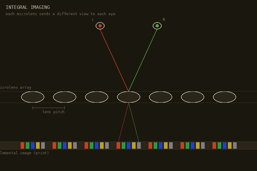
A sheet of tiny lenses sits over a high-resolution print. Each microlens covers a small cluster of pixels — the elemental image — each pixel encoding a slightly different viewing angle. The lenses redirect those rays so that your left and right eye (and any lateral movement) receive the correct perspective. Result: a reconstructed 3D image floating in or behind the lens plane.
Unlike stereoscopic 3D (two views only), integral imaging gives full 2D parallax — up/down and left/right — and avoids the vergence-accommodation conflict that causes eye strain in regular 3D cinema.
the numbers
| parameter | diy / amateur | professional |
|---|---|---|
| lens pitch | 1.0 mm (25 LPI) | 0.25 mm (100 LPI) |
| print resolution | 600 DPI | 2400 – 4800 DPI |
| alignment tolerance | ~100 µm (visible ghosting) | <15 µm (clean 3D) |
| views per lens | 5 – 10 | 20 – 60 |
The math: 50 lenses/inch × 20 viewing angles = 1000 px/inch minimum. For smooth parallax motion, 2400 DPI is the professional entry point. Standard inkjet printers top out around 1200 DPI, optimistic.
why it fails for static prints
- Moiré: printed dot pitch vs. lens pitch must match exactly or you get wavy interference patterns across the whole image.
- Thermal/humidity drift: plastic lens sheet and paper expand at different rates. A few degrees shifts pixels out from under their lenses.
- Registration: gluing a lens sheet onto a print and centering every lens over every elemental image across the whole surface is a precision manufacturing problem. Pros print directly onto the back of the lens sheet with a UV flatbed — skips lamination entirely.
lenticular vs. integral
Most "3D" prints in shops are lenticular: cylindrical lens ridges, parallax only left-right, easy to align. Integral imaging uses a fly's-eye array — thousands of tiny round bubbles — giving true 2D parallax. Aligning to a bubble grid is an order of magnitude harder than aligning to vertical lines.
artists doing it anyway
- Jeff Robb — custom 3D capture rig, dozens of angles, large-format high-DPI sheets. Calls it "sculpture in a frame."
- Patrick Boyd — active since 80s/90s, lenticular photography as spatial medium. [instagram]
- Yaacov Agam — kinetic art, physical corrugated surfaces as microlens precursor, Agamographs. [youtube]
- r/lenticular_art — makers using Python + Blender to generate elemental image grids for microlens arrays. [reddit]
- Looking Glass Factory — digital light field displays, active community, useful for previewing 3D scenes before a print.
if you were to try
- Get a fly's-eye lens sheet with known pitch (e.g. 0.5 mm). Measure it. Don't trust the spec.
- Generate elemental image grids in Blender (scripts exist) or use Looking Glass tools to preview the scene first.
- Print at 2400 DPI minimum on a UV flatbed that prints directly onto the lens sheet backing — skip lamination entirely.
- Control temperature during printing and mounting. Seriously.
- Test at postcard scale before committing to large format.