

- 1body portion
- 2tongue
- 3s de members
- 4member
- 5edge
- 6hole
- 8pointed portion
- 9members
- 11members
- 12aperture
- 14members
Description
J. P. MANYPENNY.
FINGER NAIL CLIPPER.
APPLICATION FILED JAN. 10, 1914.
1,125,577, Patented Jan.19, 1915. I
INVENTOR WITNESSES M4 ATTORNEY THE NORRIS PETERS CO. PHOTO-THO. WASHINGIUN, D. C
j time STATES PATENT ornron.
JOSEIEI-ll P. MANYPENNY, IwTERCI-IANTVILLE, NEW JERSEY.
FINGER-NAIL CLIPPER.
eam;
facture, and which shall be especially effective in use.
For an illustration of some of the forms my invention may take reference s to be had to the accompanying drawing, 111 which:
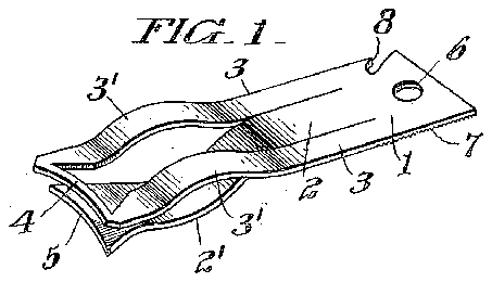
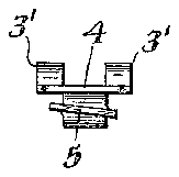
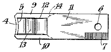
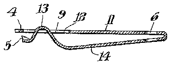
Figure 1 is a perspective view of a fingernail clipper embodying one ,form of my 1nvention. Fig. 2 is a side elevatlonal View of the clipper shown in Fig. 1. F1g. 3 1s a longitudinal sectional view, some parts 1n 7 elevation, taken through the longitudinal center of the instrument shown in Figs. 1 and 2. Fig. 4 is a front end elevation of the instrument shown in Fig. '1. F 1g. 5 is a top plan view of a modified construction. Fig. 6 is a longitudinal SBCtlOHZLhVlGW through the longitudinal center of F1g. 5. Fig. '7 is a front elevational v ew of the instrument shown in Figs. 5 and 6. 0 Referring to Figs. 1 to '4 lncluslve, 1 is the body of the clipper formed of sheet metal, preferably of steel which w1ll take a suitable temper at the cutting portlons and a spring temper at other portions. The body 1 is normally av substantially rectan- 4 gular blank piece of sheet metal from which the tongue 2 is separated or punched, 1ts one end remaining integral with the body portion 1. The separation of the tongue 2 from the body member 1 leaves the s de members 3, 3 of the body portion, these side members 3 being joined at the front end by the preferably curved narrow piece 4. With the inner edge of the HZLITOW member 4 is adapted to cooperate the front edge 5 of the tongue member 2, the cutting or clipplng edge 5 being preferably curved to correspond with the preferably curved inner cutting or clipping edge of the member 4. As shown in Fig. 4, the edge 5 is preferably lncllned with respect to the member 4, though elther Specification of Letters Patent.
' Application filed anuary 10, 1914. Serial No. 811,318.
Patented; Jan. as, rare.
or both of these members may be inclined. The sides 3 may be bowed as indicated at 3 and the tongue 2 bowed asindicated at 2, the tongue 2 and the portion 2 and the sides 3 and their parts 3 having preferably a spring temper while the parts 4 and 5 are given a temper suitable for finger nail clipping purposes. The body portion may be provided with a hole 6 for receiving a chain, hook or any other suitable means for carrying or securing the clipper. And the body portion 1 may be provided with a nail file portion 7 and a pointed portion 8 for nail cleaning purposes. Normally the parts of the finished instrument are substantially in the position indicated in the drawing. The user may place the narrow curved member 4 beneath the nail to be clipped and press downwardly upon the bow 2 and upwardly upon the bows 3 causing the members 4 and 5 to come together and, due to their inclination, pass each other at their edges and in so doing clip the nail, and upon release of the pressure of the hand or fingers upon the parts 2 and 3 the parts will assume their normal position. I
Referring to Figs. 5 to 7 inclusive, the part 4, similar to that in Fig. l, connects the ends of the members 9 and 10 formed by punching out from the upper member 11 a piece leaving an aperture 12 to allow free movement therethrough of the forward end 13-of the member 14 which carries at its forward end the cutting edge 5. Here the members 14 and 11 are integral and formed by bending back upon itself apiece of sheet metal. Normally the partsstand in the position indicated in the drawings and by applying the member 4 to the nail and squeezing members 11 and 14 toward each other the nail is clipped as described in connection with the instrument shown in Fig. 1.
While I have indicated the cooperating cutting members 4 and 5 at the front of the instrument in both modifications it is to be understood that they may be otherwise suitably located with respect to the relatively springing or moving members 2 and 3, of Fig. 1, or 11 and 14 of Figs. 5 to 7 inelusive.
What I claim is:
1. A finger-nail clipper comprising a nailengaging member, separated resilient supporting members therefor integral there-v with at its ends, a cooperating nail-cutting member, and a resilient member supportmg the same and integral with said first.
named members and movable in the space between said members.
2. A finger-nail clipper comprising a nailengaging member, a cooperating nail-cutting member integral with a tongue struck out of a sheet integral with said na'il engag,
ing member, and a supporting member for saidnail-engaging member on each side of said tongue.
3. A finger-mail clipper comprising a nailengaging member, separated resilient supporting members therefor integral there- Gopies of this patent may be obtained for I with at its ends, a cooperating nail-cutting fire cents eachpby addressingthe Commissioner of Patents,
Washington, D. c."
