- 2hunt
- 10device
- 12arm
- 14lower arm
- 16spring
- 17turning point
- 18relief openings
- 19outer end walls
- 20blade
- 22recesses
- 24notches
- 26shearing edges
- 28shearing edges
- 32upwardly projecting portion
- 34point
- 36recess
- 37point
- 38end
- 40lateral serrations
- 42openings
- 44openings
- 211is patent united states patents moore et
- 506hunt
- 999hunt
Description
- "--uumlllllllllllllllllllllllilllllllflllllllllllilfllllllll ...fimmnmumununn nmmumummulllllll /6 20 Sept. 12, 1961 J. w. HUNT 2,999,506
NAIL CLIPPER Filed. Dec. 20, 1957 I NV ENTUR.
2,999,506 NAIL CLIPPER John W. Hunt, Pontiac, Mich., assignor to Pontiac Specialties Manufacturing Corporation, Pontiac, Mich., a corporation of Michigan Filed Dec. 20, 1957, Ser. No. 704,085 8 Claims. (Cl. 132-755) This invention relates to manicure implements and more particularly to a one-piece pocket device which is a combination of a nail clipper, cleaner and file.
It is a principal object of the present invention to provide a pocket manicure implement capable of clipping cleaning and filing nails.
It is a further object of this invention to provide such an implement having a one-piece construction.
Another object of the invention is the provision of a manicure device which can be completely formed in one stamping operation and then hardened by heat treating to form a finished product without requiring additional fabricating operations such as welding, grinding, honing or assembly.
A further object of this invention is the provision of a manicure device having a pair of scissor-action cutting jaws to facilitate the clipping of finger nails on either the right Or left hand with equal ease and which are provided with guide means to aid in cutting the nails to the proper length.
A still further object is to provide a locked condition for the manicure implement when not in use thereby to protect the cutting jaws against damage and to enable the device to be carried in a pocket or ladys handbag withous danger of injury to the person or damage to his clothes.
Other objects of this invention will appear in the following description and appended claims, reference being had to the accompanying drawings forming a part of this specification wherein like reference characters designate corresponding parts in the several views.
In the drawings:
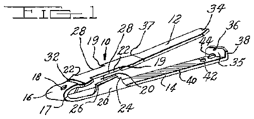
FIG. 1 is a view in perspective of one embodiment of the present invention.
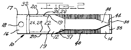
FIG. 2 is a top plan view of the FIG. 1 embodiment.
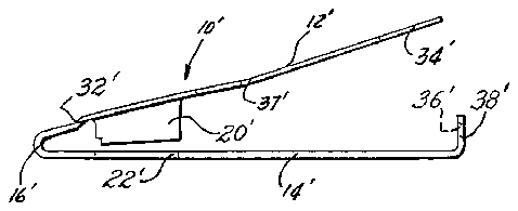
FIG. 3 is a side elevational view of another embodiment of the present invention.
Before explaining the present invention in detail, it is to be understood that the invention is not limited in its application to the details of construction and arrangement of parts illustrated in the accompanying drawings, since the invention is capable of other embodiments and of being practiced or carried out in various ways. Also, it is to be understood that the phraseology or terminology employed herein is for the purpose of description and not of limitation.
The manicure implement is formed from a strip of heat treatable metal, preferably a spring steel or the like. The continuous one-piece construction comprises an upper arm 12 and a lower arm 14 hingedly secured together at one end by means of a plate spring portion 16. The spring 16 may be provided with a plurality of relief openings 18 to control the spring rate. The spring rate may also be reduced by narrowing the width or reducing the thickness of the cross-section at the turning point 17. The
thickness may conveniently be reduced by a coining operation during the fabricating process.
As indicated in the FIG. 1 embodiment, the lower arm 14 is provided on each side, at a point adjacent the spring portion 16, with an upwardly extending shearing blade 20 which is receivable in a rectangular recess 22 provided on each side of the upper arm 12. The shearing blades 20 may be provided with notches 24 in the upper corners remote from the spring 16 to abut against the upper arm 12 and act as a stop when the arms 12, 14 are pivoted towards one another.
The shearing blades 20 and recesses 22 cooperate to act as cutting jaws for trimming finger nails. The inner surfaces of the blades 20 form shearing edges 26 which .remote from the spring 16 and proceeds towards the spring '16. This is accomplished by tapering the upper portion of the blades 20 downwardly toward the spring 16 and off-setting the arm 12 from the spring 16 by means of an upwardly projecting portion 32. The arm 12 is preferably olf-set at a point adjacent the spring side of the recesses 22. This arrangement tends to stiffen the arm 12 adjacent the spring 16 to thus move the pivot point away from the spring 16 and to increase the distance between the shearing edges 26, 28 when the device is in the normal open position. The upper arm 12 may be bent upwardly at a point 37 intermediate the recesses 22 and point 34 to provide a longer travel for the arm 12 during the shearing process.
When the arms 12, 14 are in a closed position as shown in FIG. 2, the upper surface of the shearing blade 20 is substantially flush with the upper surface of the upper.
arm 12. This arrangement provides protection for the shearing edges 26, 28 against being nicked or otherwise,
damaged when carried in a pocket or purse and also forms a smooth outer surface having no sharp projections which could damage the users clothes or person.
The manicure implement 10 may be locked in the.
point 34 to engage the recess 36. The device 10 will resume approximately its normal position when the point 34 is seated in the recess 36 thus providing a firmly locked position. There will, however, be some distortion of the device 10 which will result in the notches 24 abutting against the outer end walls 19 of the recesses 22. The resulting biasing of these surfaces aids in securely locking the device 10 in a closed position. The point 34, in addition to acting as part of the locking means, serves as a nail scraper for cleaning beneath the finger nails.
The upper surface of the bottom arm 14 may be provided with lateral serrations 40 to serve as a nail file portion. Openings 42, 44 may also be provided in one end of the arm 14 for the insertion of a key ring chain.
The embodiment illustrated in FIG. 3 is similar in all respects to the device 10 hereinbefore described excepting that the position of the shearing blade 20' and recesses 22- is reversed. The blade 20' extends downwardly from the Patented Sept. 12, .1961:
upper arm 12' and'the cooperating recesses 22' are provided in the lower arm 14". This alternate form will operate with comparable effectiveness to the embodiment previously described.
The manicure implement 10, when used as a nail clipper, may be held in one hand and a finger nail of the other hand inserted past the shearing edges 26, 28 preferably at a slightly downward angle and the arms 12, 14 pivoted towards one another. The cutting action will proceed in a scissor-like fashion from the back of the jaws forward i.e. towards the spring 16. The blade 20 acts as a guide to determine the length of the cutnail. The. extending portion of the finger nail-will thusbe ap proximately equal to thethiclgne's's' of the blade ztl. If it is desired to cut the hail shorter, the device may be turned upside down and applied with the upper surface of the blade 20 abutting against the outer surface of the nails rather than'the inner surface. Two cutting jaws are provided, one on either side of the device 10, to facilit'ate'c'lipping the nail of either the right or the left hand with equal ease. i
' The preferred method of releasing the manicure implement '10 from the locked condition is to hold it in one hand with'the index finger extended beneath the arm 14 about A; from the end. With the thumb extended, pressure-is exerted on the point 34 and upturned end 38 thus distorting these parts and forcing them apart. Due-to the action of the spring 16 the arm 12 will move away from and out of engagement with the end 38.
To use the device 10 as a nail cleaner, it is preferable to hold it with the index finger wedged between the arms 12, 14 thus forcing them further apart and providing finger clearance about the point 34. The pressure of the arms 12 14 against the index finger will aid in securing the device 10 in this nail cleaning position.
The clipper as described is thus seen to be inexpensively constructed and effective in use. The one piece structure and'the over all design of the cooperating parts permits the clipper to be fabricated in one operation by, for example, a progressive or follow die. This reduces the tooling and fabrication costs with a resultant low unit cost per manicure implement. 7
Having thus described by invention, I claim:
'1. A manicure implement having a continuous onepiece construction comprising upper and lower arms hingedly secured'together at one end by means of a spring portion, said lower arm being provided along at least one longitudinal side edge at a point adjacent the spring portion with an upwardly projecting shearing blade, the upper marginal edge of said blade being tapered downwardly towards said spring portion and forming a shearing edge, said upper arm being provided with a recess extending inwardly from at least one longitudinal side edge with the lower margin of the longitudinal wall forming a shearing edge, the distal portion of said upper arm being oiIf-set upwardly from the remainder of the arm at a point adjacent to the spring side of said recess, said recess being adapted to register with and receive said shearingblade in'overlapping fashion when said arms are pivoted towards each other to form a nail cutting jaw having a cutting action which proceeds from a point remote from said spring towards said spring.
2. A manicure implement having a continuous onepiece construction comprising upper and lower arms hingedly secured together at one end by means of a spring portion, said lower arm being provided along each longitudinal side edge at a point adjacent the spring portion with an upwardly projecting shearing blade, the upper marginal edges of said blades being tapered downwardly towards said Spring portion and forming a shearing edge, said upper arm being provided with a recess extending inwardly from each longitudinal side edge with the lower margins of the longitudinal walls forming shearing edges, the distal portion of said upper arm being ofifeset upwardly from the remainder of the arm at a point adjacent to the spring side of said recesses, said recesses being adapted to register with'and receive said shearing blades in overlapping fashion when said arms are pivoted towards each other to form nail cutting jaws having a cutting action which proceeds from a point remote from said spring towards said spring, said shearing blades being provided with a notch in the upper corners remote from said spring to engage and stop said upper arm at the end of the cutting action with the upper surface of said blades substantially flush with the upper surface of said upper arm.
3. An implement as claimed in claim 2 and further characterized by the provision of an upturned tab on the distal portion of the lowerarm having its inner face slightly closer to thespring portion than the free end of said upper arm, said upper arm being formed with a nail scraping point at its free end adapted to lockingly seat in a recess provided in the innerface of said'upturned end and to deform said implement to bias said notches against said upper arm thereby to securely lock said implement in a closed position.
4. A device as claimed in claim 2 and further characterized by the provision of lateral serrations on thetowards said spring portion and forming a shearing edge,
said lower arm being provided with a recess extending inwardly from each longitudinal side edge with the lower margins of the longitudinal walls forming shearing edges, the distal portion of said upper arm being off-set upwardly from the remainder of the arm at a point adjacent to the springside of said blades, said recesses being adapted to register with and receive said shearing blades in overlapping fashion When said arms are pivoted towards each other to form nail cutting jaws having a cutting action which proceeds from a point remote from said spring, towards said spring.
6. A manicure implement having a continuous onepiece construction comprising upper and lower arms hingedly secured together at one end by means of a spring portion, said upper arm being provided along each longitudinal side edge at a point adjacent the spring portion with a downwardly projecting shearing blade, the lower marginal edges of said blades being tapered upwardly towards said spring portion and forming a shearing edge, said lower arm being provided with a recess extending inwardly from each longitudinal side edge with the lower margins of the longitudinal walls forming shearing edges, the distal portion of said upper arm being ofii-set upwardly from the remainder of the arm at a point adjacent to the spring side of said blades, said recesses being adapted to register with and receive said shearing blades in overlapping fashion when said arms are pivoted towards each other to form nail cutting jaws having a cutting action which proceeds from a point remote from said spring, towards said spring, said shearing blades being provided with a notch in the lower corner remote from said spring to engage and stop said lower arm at the end of the cutting action with the lower surface of said blades substantially flush with the lower surface of said lower arm.
7. Ant implement as claimed in claim '6 and further characterized by the provision of an upturned tab on the distal portion of the lower arm having its inner face slightly closer to the spring portion than the free end of said upper arm, said upper arm being formed with a nail scraping point at its free end adapted to lockingly seat in a recess provided in the inner face of said upturned. end and to. deform said implement to bias said notches against said lower arm thereby to securely lock said implement in a closed position.
8. A device as claimed in claim 6 and further characterized by the provision of lateral serrations on the upper surface of the lower arm to serve as a nail file. 5
References Cited in the file of this patent UNITED STATES PATENTS Moore et 211. June 28, 1892 10 Nash Mar. 9, 1897


