

- 5lines
- 6lines
- 7lines
- 8line
- 10member
- 11member
- 12lever
- 13pivoted hook member
- 14end
- 15opening
- 16cutting surfaces
- 18pivoting lugs
- 19slots
- 20overhanging hook portions
- 21bearing piece
- 23catch
- 24pivoting lugs
- 25openings
- 26sidewall portions
- 27file face
Description
H. SIMS.
NAIL CLIP.
APPLxcATmN man MAY 21. 191s.
4Pammrbed Jaun; 7, 19M).
INVEN QR ma mamas mzrmns m.. rmrmuma. wmmncm. n. c
PATENT OFFICE.
RICHARD SIMS, 0F NEWARK, NEW JERSEY.
NAIL-CLIP.
incasso. y
Speccation of Letters Patent.
Patented J an. *7, 1919.
Application led May 27, 1918. Serial No. 236,690.
To all 'whom t may concern Be it known that I, RICHARD SIMS, a citizen of the United States, and a resident of Newark, county of Essemand State of New Jersey, have invented certain new and useful Improvements in Nail-Clips, of which the following is a specification. t
This invention relates to nail clips. v
An object of the invention is to provide a clip of simple form which can be easily and cheaply constructed and which can be readily assembled and taken apart without the use of tools. t
The invention further has for its object the improvement of devices of this character in a number of important respects, and with the foregoing and related objects in view, my invention consists in the parts, improvements, combinations and features of lconstruction herein set forth and claimed.
ln the drawing forming part ofthis specific-ation and wherein the same reference numerals are uniformly applied to designate the same parts throughout, I have illustrated an embodiment of my invention for the purpose of adording a clear understandingV i thereof, but Jit is to be understood that the same is for the purpose of illustration only and not for limitation of the invention.
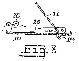
In said drawing Figure 1 is a side view of the nail clip in closed position. Figs. 2 and 3 are-end views taken from opposite ends. Fig. 4 is a plan view. Figs. 5, 6 and 7 are longitudinal sectional views taken substantially on the lines 5, 6, 7 5, 6, 7, Fig. 4, and showing different positions of the clip elements. Fig. 8 is a longitudinal sectional view taken substantially on the. line 8 8, Fig. 4, and showing the preferred form of connection between the cutting elements of the clip. Figs. 9 and 10 are fragmentary bottom and top plan views of the operating lever which is also adapted to serve as a nail cleaner and nail file.
The nail clip of the present invention consists of but three principal elements, the cutting elements 10 and 11 and the lever 12. There is also, in the form illustrated, a
r fourth element, namely, the pivoted hook member 13, but other forms of retaining hooks may be made use of, as, for example, the end of the element 10 may be made into a retaining hook if desired.
Such three main elements are interchangeable and may be assembled without the use of tools, rivets or anything of the kind. To
assemble, the oifset end 14 of the cutting element 11 is introduced into the opening 15 in the cutting element 10, substantially as shown in Fig. 8, and is pressed downwardly against its tendency to spring upward so that the cutting surfaces 16 and 17 are brought substantially together, the offset end 14 passing through the opening 15 serving to position the cutting edges correctly opposite one another. The lever 12 is then pushed downwardly and forwardly so that the pivoting lugs 18 formed thereon enter the curved slots 19 provided for this purpose at each side of the member 10. The spring action of the member 11 serves to hold the lever 12 upwardly with the pivoting lugs 18 engaging against the overhanging hook portions 20, 20 formed above the slots 19, 19. So assembled, the device is ready for operation and the parts will remain in the relative relations in which assembled until purposely disassembled, which may be done by substantially reversing the acti`on just described, pushing the lever 12 downwardly and rearwardly to overcome the upward spring action of the member 11 and withdrawing the pivoting lugs 18 from the slots 19.
The device is operated in the usual manner by means of the lever 12 which has a bearing piece 21 contacting with the upper surface of the member 11 and serving, when the lever 12 is depressed, to force its cutting edge 1G downward against the cutting edge 17 of the member 10.
When a separate hook is provided it mayT be formed as shown at 22, of substantially U form with a catch 23 and pivoting lugs 24, 24. The pivoted hook is permanently assembled to the member 10 and this may be done by making the legs of the U-shaped portion thereof somewhat converging prior to assembly and the legs of the U-shaped member may be spread apart to cause the pivoting lugs 24 thereof to enter the openings 25 in thevmember 10. Such openings are preferably provided in sidewall portions 26 of the member 10 which may also contain the slots 19 though, if desired, separate upward extensions of the member 10 at the sides thereof may be provided for such purposes.
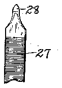
The under side of the lever 12 is preferably provided with a file face 27 and the end thereof is preferably pointed as indicated at 28 to form a device for cleaning under hold`the-member12in open position for use asI-a filing and. cleaning tool.
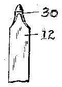
When the devicel is to'y be. putv awayy as in the pocket, the lever l2 is pushed down againsttherspring member 11 and the catch 23 ofI the hook lengaged with the notch 30-in the member 12 to retain theV parts in closed position as shown in Figs; 1 and2'.
It will' lie-'understood that such terms as upwardly, forwardly, backwardly 'and thelike, as used herein, haverelative significancef only; v
I-t'will' be seen: that a nail clip in accordance with my invention possesses numerousV features of'fadvantage. The parts are interchangeable andwhen any thereof is broken it maybe replaced;I assembly and disassembly being accomplished by' simple manual movements, the usual cost of assembly involving heading'over of rivets and the like is substantially eliminated; when it is desired to sharpen the cutting knives they may be exposed for ready ing the device to pieces, and it can readily be reassembled after the sharpening operation is completed, and the operating lever, which, when open, serves the function of a nail file and cleaning tool, is positively held in such open position, substantially as in the case of the blade of an ordinary pocko: knife. l
I claim:
In a nail clip, a cutting member having an opening therein and having sidewall portions provided with open-ended rearwardly directed slots, a second cutting member having its rear end offset and removably received in said opening and having a spring tendency away from the first cutting niember,.and an operating lever having pivoting lugs adapted to be removably received in said slots and having a backwardly turned arnn for engagingy the second cutting niember, whereby the cutting members and operating lever may be completely assembled and disassembled manually and without the use of tools.
In testimony that I claim the foregoing, I have hereto set my hand, this 20th day of May, 1918.
RICHARD siMs.
Copies ofy thispatent may be obtainedJfor five cents each, by addressing the Commissioner of. Patents,
Washington, D. C.
access by simply takif'
