- 5bottom blade
- 6jaw
- 10pivot pin
- 11head
- 12deep under-cut notch
- 13cross-bar
- 14operating lever
- 15.nail file
- 16eyelet rivet
- 20or fulcrum surface designated generally
- 21projections
- 22projection
- 23lands
- 24projections
- 25projection
- 26upper jaw
- 31hole
- 35upper blade
- 36projection
- 37lands
- 38projection
- 39operating lever
- 40projections
- 41surface
- 45hole
- 2491949 foreign patents
- 2891949 foreign patents
- 3791956 w bassett
- 383patent united states patents
- 843patent united states patents
Description
March 27, 1956 w BASSETT 2,739,379
NAIL CLIPPER Filed May 20, 1955 INVENTOR ATTORNEYS llnited States Patent NAIL CLIPPER William E. Bassett, Woodbridge, Conn.
Application May 20, 1953, Serial No. 356,131
Claims. (Cl. 30-28) My invention relates to a nail clipper of the general type shown in my Patent No. 2,477,782, August 2, 1949.
Nail clippers are made in different sizes; the largest sizes being generally preferred as toe-nail clippers while the smaller sizes are most often used on the finger-nails. The usual form of the cutting edge of a nail clipper of the type referred to is concave so as, generally speaking, to follow the more or less natural convex shape of the finger nail as usually clipped. However, when a nail of substantially greater width than the width of the clipper is encountered, it is sometimes diflicult to do a neat clipping job for the reason that the corners of the concave cutting edges sometimes dig into the nail at both sides, instead of clipping it off cleanly. I provide a different shape in my improved clipper to avoid that difliculty.
Nail clippers of the type referred to are, in general, more or less unstable in the hand for the reason that the actuating lever and the bottom blade are engaged by one or more of the fingers and the thumb and, since the lever is pivoted to the blades at the end remote from the gripped portions, the lever is likely to swing or yaw about the pivot pin and cause annoyance to the user particularly when he has the clipper in a somewhat awkward or unusual position as, for instance, when cutting the toe-nails.
It is an object of my invention, therefore, to provide a nail clipper which is not likely to dig into the nail at the corners.
It is another object to provide a nail clipper having a straight or somewhat convex contour at the cutting edges so that a nail of any width may be safely clipped without danger of digging in at the corners.
It is another object to provide a nail clipper in which the operating lever is so related to the jaws or blades and the pivot pin that there is little or no likelihood that the lever will turn or yaw on its pivot pin axis accidentally during a clipping operation.
Other objects and features of novelty will be pointed out or will become apparent to those skilled in the art.
The invention may be embodied in various forms, some of which will be herein disclosed.
In my improved clipper, I provide interengaging means between the actuating lever, the pivot pin and the jaws or blades so that the lever, when in operative position, will not accidentally swing about the pivot pin connecting the two blades and the lever.
In the drawings which show, for illustrative purposes only, preferred forms of the invention:
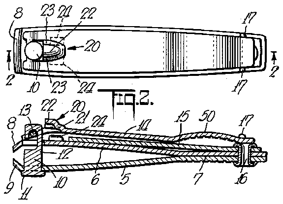
Fig. l is a top plan view of a nail clipper embodying features of the invention;
Fig. 2 is a central vertical sectional view of the clipper shown in Fig. 1;
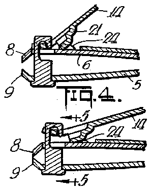
Fig. 3 is a fragmentary sectional view similar to Fig. 2 but illustrating the operating lever in operative position rather than in the folded or inoperative position as shown in Figs. 1 and 2;
Fig. 4 is a view similar to Fig. 3 but illustrating the lever depressedand the cutting edges of the jaws pressed 2,739,37Q Patented Mar. 27, 1956 tightly together as at the end of the clipping operation;
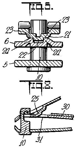
Fig. 5 is an enlarged sectional view taken substantially in the plane of the line 5-5 of Fig. 4;
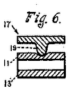
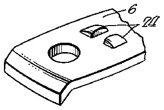
Fig. 6 is a fragmentary, enlarged, isometric View of what may be termed the top jaw or blade which is next to the operating lever;
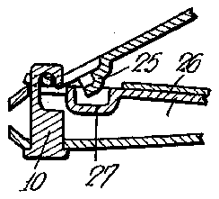
Fig. 7 is a view similar to Fig. 3 but illustrating a slightly modified form;
Fig. 8 is a view similar to Fig. 7 but illustrating a further modification;
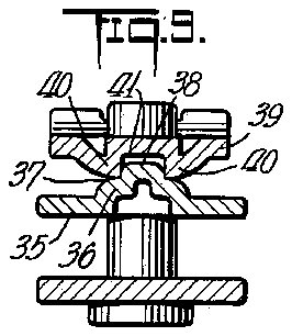
Fig. 9 is an enlarged cross-sectional view similar to Fig. 5 but illustrating a further modification; a
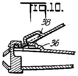
Fig. 10 is a view similar to Fig. 3 but illustrating still another modification; and
Fig. 11 is a view similarto Fig. 10 but illustrating still another form.
Referring to the drawings, and particularly to Figs.
1 to 6, all of which illustrate diflerent parts or positions of the same particular form of the invention, 5 indicates what may be termed a bottom jaw or blade while 6 is the top jaw and the two jaws are rigidly secured together at the rear as indicated at 7 by being welded or otherwise secured together. The jaws are of spring material and are sprung apart; the front edges 8-9 are sharpened as is usual in clippers of this type. The cutting edges 8-9 are not formed concave as in the usual nail clippers but are formed more or less convex as indicated.
in Fig. 1.
The jaws adjacent the front or clipping end are apertured as is usual for the connecting pin 10 which pin has a head 11 engaging the bottom blade 5 and which has a side-opening, deep under-cut notch 12 therein which notch receives the cross-bar 13 provided on the operating lever 14 in the usual fashion. In the positions illustrated in Figs. 1 and 2, the operating lever is in what may be termed the inopertive or folded position in which the jaws by their springiness tend to open up and hold the lever 14 in place over the top of the top blade 6 as illustrated in Fig. 1. In the form shown, the .nail file 15 which is ,pivotally mounted as by means of an eyelet rivet 16 at the rear of the jaws has upstanding ears 17-17 to embrace opposite sides of the lever 14 to further hold it in place while the entire clipper is in its inoperative or non-clipping position. Clippers of the present type usually have a projectng cam or fulcrum member close to the front end and when it is desired to operate the clipper the operating lever 14 is raised slightly at the rear and swung about the pivot pin 10 so that the pivot pin turns about and the operating lever is then swung back in a vertical arc and then occupies a position about as shown in Fig. 3. When the operating lever is depressed to the position shown in Fig. 4, the cutting edges of the blades are brought together as shown in Fig. 4 since the fulcrum member or cam engages the top blade all as is well known in the art.
As heretofore indicated, my invention contemplates the provision of means for preventing the operating lever from accidentally swinging sideways or yawing when the lever has been turned to operative position as shown in Figs. 3 and 4.
In the form illustrated in Figs. 1 to 6, the cam or fulcrum surface designated generally 20 is preferably formed as a substantial projection formed up as indicated at 21 and the formed up portion is further formed up centrally as indicated at 22 leaving what may be termed flats or lands 23 at the opposite sides of the central projection 22. As shown in Figs. 1 to 6, the top jaw is provided with a pair of struck up projections 24-24 spaced apart laterally of the jaw 6 by an amount sufficient to permit the struck up central section 22 on the operating lever to engage freely between them. The land surfaces 23-23 preferably engage the tops of the projections 24 24 as illustrated particularly in Fig. 5 while the projection 22 is located between the struck up guide or abutment members 24-44. The struck up guides 24-24 are abutments and the struck up projection 22 has fairly abrupt sides, so that when the projection 22' lies between the guiding projections 2424, the springiness of the two jaws holds the lever and the upper jaw 6 in position and the operating lever is thus prevented from accidentally turning on the pivot pin 10 during the In the form shown in Figs. 1 to 6,
or cam surface and as a guide or holding means against accidental swinging of the operating lever relatively to the blade about the axis of the pin 10.
In that form of the invention shown in Fig. 7, the cam or fulcrum projection is made much deeper than the projections 21 and 22 of the form previously described. The upper jaw 26, instead of having projections like the projections 24, has a dimple or depression 27 formed in the top thereof and the projection 25 is designed to enter the dimple 27 and the lands corresponding to the lands 23 on the operating lever are designed to engage the top surface of the upper blade 26. Thus, the projection 25 may correspond in substantially every way with the projections 21- 22 of the form shown in Figs. 1 to 6, but both projections are made deeper so that the projection 25 enters the dimple and the lands ateach side of the projection 25 rest directly on top of the jaw 26 and thus operate in much the same manner as the'other form and the deep drawn portion of the projection fits in the dimple and prevents sidewise swinging or yawing of the operating lever about the pivot pin 10.
In the form shown in Fig. 8, the construction of the operating lever may be and preferablyis exactly the same as that shown in Fig. 7 but the upper jaw 30, instead of having a mere dimple therein, has a hole pierced all the way through so that the high part of the projection 25 on the operating lever extends into the hole'31 so as to prevent turning or yawing of the operating lever about the pin 10 and the portions corresponding to the lands 23 rest on the top of the blade 30 at each lateral side of the hole 31. Thus, the operation of the form shown in Figs. 7 and 8 andeven the constructions are almost identical; the difference being only in the form of the dimple or hole or depression in the top jaw or blade. At this point it might be'said, however, that instead of having the lands beside the projection 25 in Fig. 7 acting on top of the blade 26, the high projecting portion 25 could act on the metal at the bottom of the dimple and thus the high projection 25 would serve the double function of actuating the upper jaw 26 and at the same time preventing twisting or yawing of the operating lever.
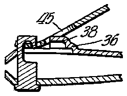
In that form of the invention shown in Fig. 9, the upper blade instead of having a dimple or a depression or simply being flat has a punched up or raised projecting portion 36 providing flat surfaces or lands '37 and a central projection 38' intermediate the lands 37. The operating lever 39 is provided with a pair of struck up projections 4049 corresponding more or less to the struck up lugs or projections in the form shown in Figs. 1 to 6. These projections 4tl4tlare spaced apart so as to embrace the struck up projection 38 and thus prevent yawing of the operating lever 39 during the operation of the clipper. The projections 40-40 furthermore are designed to act on the lands 37-37 to-bring' the two.
jaws together. It will be clear that, if-desired,-the center projection on the upper blade 35 could be made deeper still-and could-engage the surface 41 of the operating lever between the projections 40-4-0 and thus the projections 38 and surface 41 would actuate the upper blade and the projections 40 and the projection 38 acting laterally against each other would prevent yawing or twisting of the operating lever. A
In that form shown in Fig. 10, the projections 36 and 38 are much deeper than in Fig. 9 and the lever has a dimple or depression to receive the deep projection 38 to prevent swinging or yawing as heretofore described and the lands on the projection 36 may engage the underside of the lever at oppositesides of the dimple to actuate the jaws. Here again it maybe stated'that the projection 38 may engage the bottom of the dimple and thus serve as a cam or fulcrum surface as well as prevent the swinging or yawing of the lever.
in the form shown in Fig. 11, the projection 36 and the center projection 38 may be identical with those correspondingprojections in the form shown in Fig. 10. The operating lever in the form of Fig. 11, however, in-
stead of having a dimple to house, the projection 38 has a hole '45extended therethrough, which hole receives the upper projection 38 while the lands on the projection 36 and corresponding to the lands 37 of Fig. 9 act onthe side of the lever adjacent the hole itself. It will be seen, therefore, thatin Figs. 10 and ll, the jaw construction is substantially the same because the projections on the blade ineach instance preferably act on the fiat surface of the operating leverand it is only the high projection- 38 which tits in the hole 45 in Fig. 11 or the dimple in Fig. 'l-O; In the form shown in Fig. 9, on the other hand, thereare projections on both the blade andthe operating leverwhich act on each other for actuating the upper It will be seen, therefore, that I have provideda nail clipper which operates more or less in the manner of all nail clippers of this generaltype, but there is little or no danger of having the operating lever swing about or yaw about (the pivot'pin and thus throw the cutting edge to various angles which might be dangerous to the toe'or finger where the nail is being clipped, and this is true regardless of the position of the nail clipper or howit is' held or in what manner operated.
In order tofurther facilitate opera-tion of the clipper,
I prefer to make a slight bow or depression near the. end
of the operating lever as indicated at'50 in Figs. 1 and 2. This bow forms a general depression for the thumb or any part of the hand when the operating lever 14 is turned around and swung around into operative position. Furthermore, it is preferred to have the bow or depression 50 slightly knurled or roughened so as to tend to prevent slippage of the hand thereon andthe bottom jaw, generally opposite the bowed portion 50, is also preferably knurled so. as to provide a better grip.
While the invention has been described in considerable detail and preferred forms illustrated, it is to be understood that various changes and modifications may be made within the scope of the invention as defined in the apsaid members having integral struck-up abutment means defining a pair of spaced apart generally vertical abutmentsurfaces for cooperation withsaid first mentioned generally vertical abutment surfaces, .the said integral struck-up abutment means on the said other member defining -a'pair of spacedv apart generally horizontal abut- 1118111 surfaces for cooperation with said -firstmentioned generally horizontal abutment surfaces, for the purpose set forth.
2. In a nail clipper of the character indicated, a jaw member, a lever member for cooperation therewith, a pivot pin at generally right angles to said jaw member and lever member and connecting the same together and permitting relative swinging of said members through a wide angle, one of said members having integral struckup abutment means defining spaced apart generally vertical abutment surfaces and spaced apart generally horizontal abutment surfaces, the other of said members having generally vertical integral abutment surfaces for coaction with said first mentioned generally vertical abutment surfaces to resist swinging of said jaw and lever members, and said other of said members further having spaced apart generally horizontal abutment surfaces for coaction with said first mentioned generally horizontal abutment surfaces for coaction with each other to urge said jaw member in cutting direction.
3. In the combination defined in claim 2, said other of said members having a depression therein registering with said integral struck-up abutment means, said depression defining said generally vertical abutment surfaces on the said other member and the generally horizontal abutment surfaces on the said other member being at opposite sides of said depression.
4. In the combination defined in claim 2, said other of said members having an opening therethrough registering with said integral struck-up abutment means, the sides of said opening constituting said generally vertical abutment surfaces on the said other member, and the generally horizontal abutment surfaces on the said other member being at opposite sides of and bordering said opening.
5. In a nail clipper of the character indicated, a jaw member, a lever member for cooperation therewith, a pivot pin at generally right angles to said jaw member and lever member and connecting the same together and permitting relative swinging of said members through a wide angle, one of said members having integral struckup abutment means defining spaced apart generally vertical abutment surfaces and at least one generally horizontal abutment surface, the other of said members having a depression therein registering with said integral struck-up abutment means, said depression defining two generally vertical abutment surfaces for coaction with said first mentioned verticalabutment surfaces to limit relative swinging of said jaw member and lever members about said pivot, said depression further defining at least one horizontal abutment surface for coaction with said first mentioned horizontal abutment surface to move said jaw in cutting direction.
References Cited in the file of this patent UNITED STATES PATENTS 843,383 Wooster Feb. 5, 1907 1,081,896 Eckler Dec. 16, 1913 1,085,569 La Casse Jan. 27, 1914 1,290,380 Sims Jan. 7, 1919 1,849,592 Schnefel Mar. 15, 1932 2,460,522 Miller Feb. 1, 1949 2,477,782 Bassett Aug. 2, 1949 FOREIGN PATENTS 249,289 Great Britain Mar. 25, 1926


