


- 1swivel pin
- 10combined clipper
- 12clipper end
- 13,239 5/ 1963 loda 30-142 foreign patents
- 14fingernail clipper
- 16bottom member
- 18flat lower surface
- 20correspondingly fiat upper surface
- 28pin
- 30opening
- 32upper cutting member
- 36bar
- 38operating lever
- 40opening
- 44element
- 47ett 30-2f 2,774,138 12/1956 gowdey 30-2e
- 50pin
- 52notch
- 54transverse bar
- 58ulcrum projection
- 62aperture
- 64upwardly arojecting cutting element
- 666 2? 'v
- 68:he sharpened edges
- 72aperture
- 74opening
- 76file
- 78roughened surface areas
- 79rounded beveled end
- 80projection
- 82diametrically opposed indentations
- 88y 30-2e 3,042,047 7 1962 plaskon 30-28 x
- 110clipper
- 116bottom cutting member
- 122slightly beveled surface
- 132top cutting member
- 138operating lever
- 142ka fulcruming member
- 144depending cutting member
- 146sharpened lower edge
- 204y 30-2e 3,042,047 7 1962 plaskon 30-28 x
- 242ates patents 775,568 1l/l904 lamay 30-2l
- 315 united states patent o
- 354 united states patent o
- 564,239 5/ 1963 loda 30-142 foreign patents
- 568examiner united states patents
- 615ates patents 775,568 1l/l904 lamay 30-2l
- 774in 30--25 2,739,379 3/1956 bassett 30-2f
- 775examiner united states patents
Description
FINGERNAIL AND CUTICLE CLIPPER April 25, i967 COMBINED Filed May 28, 1965 Fig. 5 ,[6 a 7? 7,6
24 79 l lM Fig. 6 2? 'v 66 /28 M2 f3@ 0 /28 @av/0 J. Oaes, Jr. Fig 7 m W48 INVENTOR.
/22 WWW l,
United States Patent O 3,315,354 COMBINED FINGERNAIL AND CUTICLE CLIPPER David J. Oates, Jr., 800 S. Pine St., Rocky Mount, N.C. 27801 Filed May 28, 1965, Ser. No. 459,742 3 Claims. (Cl. 30-28) The present invention generally relates to a device for clipping cuticles, hangnails and the like and may be constructed as an independent clipper or combined with a fingernail clipper so that a person utilizing such a device may not only clip their fingernails but also clip their cuticles and hangnails if such are present.
An object of the present invention is to provide a clipper including a pair of cooperating cutting elements that are urged towards each other by an operating lever employing a fulcruming action. In order to effectively clip cuticles, the bottom element of the clipper is substantially straight longitudinally for orientation along the top surface of a fingernail. The end edge of the bottom cutting element is curved in a convex nature for conforming generally with the curvature of the cuticle around the edge of the fingernail. Also, the bottom cutting element is transversely curved in a concave manner to further enhance its conformance with the transverse curvature of the top surface of a fingernail so that the bottom cutting element may be orientated in an optimum position for sliding slightly under the cuticle for clipping thereof. The end edge of the bottom cutting member is beveled along its bottom edge for easier insertion under the cuticle. The upper cutting element is provided with a depending cutting element that is curved in conformity with and complementary to the bottom cutting element for association therewith so that a cuticle, hangnail or the like disposed against the top surface of the bottom cutting member will be effectively severed by the top cutting member when it is forced downwardly into engagement therewith by the fulcruming action of the operating lever. Accordingly, it is an object of the present invention to provide a clipper for cuticles, hangnails or the like that is particularly constructed in accordance with the foregoing but yet which is relatively simple in construction, easy to use, effective for its particular purposes and relatively inexpensive to manufacture.
Yet another object of the present invention is to provide a clipper in accordance with the preceding paragraph that is combined with a fingernail clipper of more or less conventional construction with the fingernail clipper and cuticle clipper being orientated in end to end relation with the ends of the operating levers being disposed in overlapping nested relationship to each other and engaged with a 'stationary pin which will effectively releasably retain the operating levers in their inoperative position in superimposed relationship to each other.
Still another important object of-the present invention is to provide a combined fingernail clipper and cuticle clipper having a file associated with the bottom member thereof which is substantially fiat for positioning under the bottom surface of the bottom member or projecting longitudinally therefrom in an operative condition with means being provided for releasably securing the file in its'two positions thereby providing a combination'implement for clipping the fingernails, filing the fingernails, cutting cuticles, cutting hangnails or the like with the implement being easily operated by the individual user as easily and efficiently in one hand as the other.
These together with other objects and advantages which will become subsequently apparent reside in the details of construction and operation as more fully hereinafter described and claimed, reference being had to the accompanying drawings forming a part hereof, wherein like numerals refer to like parts throughout, and in which:
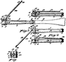
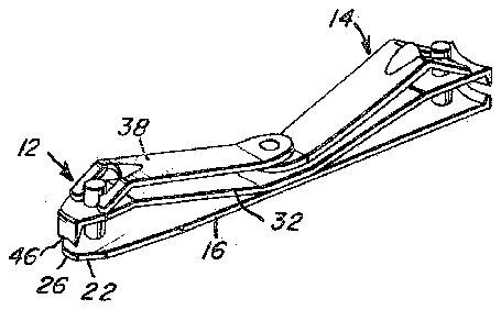
FIGURE l is a perspective view of the combination cuticle and fingernail clipper of theA present invention;
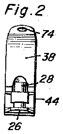
FIGURE 2 is an end View of the cuticle clipper end of the device with the operating handle therefor in 0perative position;
FIGURE 3 is a top plan view of the construction of FIGURE 2;
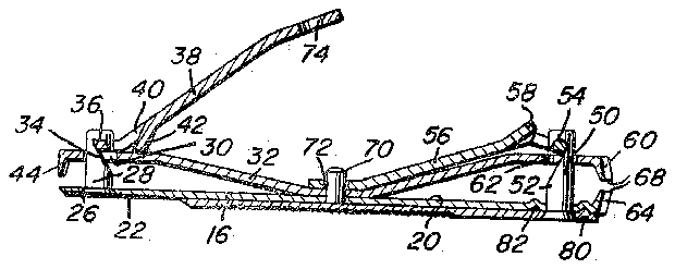
FIGURE 4 is a longitudinal, vertical sectional View taken along a section line passing longitudinally of the center o f the construction of FIGURE 3;
FIGURE 5 is a bottom plan view of the construction of FIGURES 1-4;
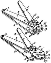
FIGURE 6 is a side elevational view illustrating a cuticle clipper constructed in accordance with the present invention without it being combined with the fingernail clipper; and
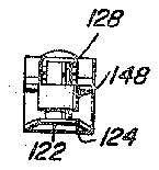
FIGURE 7 is an end view of the construction of FIGURE 6.
Referring now specifically to the drawings, the numeral 10 generally designates the combined cuticle clipper and fingernail clipper of the present invention with the cuticle clipper construction being orientated at one end thereof l and designated by the numeral 12 and the fingernail clipper construction being orientated at the other end and being designated by the numeral 14.
The combined cuticle clipper and fingernail clipper includes a single -bottom member 16 having a flat lower surface 18 and a correspondingly fiat upper surface 20. At the cuticle clipper end 12 of the implement, the bottom member 16 is beveled or tapered upwardly and outwardly as at 22 and is conveXly `rounded as at 24 as illustrated in FIGURE 5. Further, the end portion vof the bottom member 16 is transversely concave as indicated by the numeral 26 and as illustrated in FIGURE 4 and FIGURE 2 with this construction enabling the bottom surface of the bottom member 16 to conform to the natural curvature of the top surface of a fingernail when the bottom member 16 is orientated generally in longitudinal alignment with the fingernail and against the top surface thereof.
Projecting upwardly from the bottom member 16 adjacent. the cutting end edge thereof is a pin 28 which has its head countersunk into and iiush with the bottom surface of the bottom mem-ber 16 thereby eliminating any projections and providing a completely smooth eX- ternal or bottom surface to the bottom member 16. The pin 28 projects upwardly through an opening 30 in an upper cutting member 32 and the pin 28 terminates in an upwardly inclined slot 34 for receiving a transverse bar 36 on an operating lever 38. The operating lever 38 is provided with an opening 40 adjacent the bar 36 s0 that the bar 36 may be engaged and disengaged with the inclined notch 34 by deflecting the upper cutting member 32 towards the bottom member 16. Also, the operating lever 38 is provided with a projection 42 forming a fulcruming point in movable engagement with the upper surface of the upper cutting member 32 so that when the operating lever 38 is in the position illustratedV in FIGURE 4, downward pressure on theA free end thereof will cause the upper cutting member 32 to move towards the bottom member 16.
The outer end of the upper cutting mem-ber 32 is provided with a depending cutting blade or element 44 that is provided with a sharpened lower edge that is concavely curved from edge to edge to conform with the curvature of the upper surface of the lower cutting member 16 at the clipper end 12 of the implement, which end of the member 16 is transversely concaved as previously set forth at 26. The concave curvaturev of the itting blade or element 44 is designated at 46 and also,
e cutting element 44 is transversely convexly curved at 48 for conforming with the convex rounded edge l of the bottom cutting member 16. Thus, when the Jerating lever 38 is orientated in the position illustrated FIGURE 4 and the free end thereof is depressed, the
Jper cutting element 32 is depressed downwardly and le cutting element 44 will cut any material disposed etween the upper surface of the curved upper surface E the bottom cutting member 16. The specific configuraon of the cutting elements is such that cuticles may be asily clipped thereby.
The fingernail clipper 14 is somewhat of conventional onstruction in that the bottom member 16 is provided with an upstanding pin 50 extending therethrough which as a notch 52 extending upwardly and inwardly from he inner edge thereof for receiving a transverse bar 54 in an operating lever.56 which is also provided with a ulcrum projection 58 for engagement with the upper lutting member 32 which has a downturned end portion i integral therewith and has an aperture 62 movably eceiving the pin 50. The corresponding end of the ott-om cutting member 16 is provided with an upwardly arojecting cutting element 64 both of which are concavely :urved as indicated by numeral 66 and which are inclined slightly outwardly as illustrated in FIGURE 4 so that :he sharpened edges 68 thereof may engage opposite sides 3f a fingernail for clipping thereof in a conventional known manner. The central portion -of the upper cutting member 32 is inwardly bowed and is secured to the bottom cutting member 16 at the center thereof as lby spot welding or the like. A positioning pin 70 is lixedly secured to the bottom member 16 and extends therethrough and through the top cutting member 32 and also extends through aperture 72 in the free end portion of the operating lever 56 and an opening 74 in the free portion of the operating lever 38 so that when the operating levers 38 and 56 are orientated in the overlapping inoperative position illustrated in FIGURE l, the pin or locating tag 70 will retain the operating levers in place.
Orientated below the bottom cutting member 16 is a file member 76 having roughened surface areas 78 which are conventional in such a file and the headed end of the pin S0 is countersunk in the file and the portion of the file 76 adjacent the outer edge thereof is provided with a projection 80 for engagement with one of a pair of diametrically opposed indentations 82 formed in the bottom member 16 for resiliently retaining the file 76 in either its inoperative position along the undersurface of the bottom member 16 or in its operative position with the file 76 forming a longitudinal extension of the combined cuticle and fingernail clipper.
FIGURES 6 and 7 illustrate an embodiment of the invention designated by numeral 110 which is in the form of a cuticle clipper alone and which includes a bottom cutting member 116 and a top cutting member 132. The bottom cutting member 116 has a slightly beveled surface 122 and is transversely flat but curved convexly in a horizontal plane as designated at 124. The top cutting member 132 has a depending cutting member 144 integral therewith and provided with a sharpened lower edge 146 which is straight transversely but which is arcuately convexly curved as at 148. An operating lever 138 which is the same as the operating lever 38 is provided except that the operating lever 138 is substantially straight but slightly curved. kA fulcruming member 142 is provided on the operating lever 138 and the operating lever 138 is detachably and pivotally connected to a swivel pin 1.28 whichl is substantially the same as the swivel pin 28 in the structure illustrated in FIGURES 1 5. The ends of the cutting members 116 and 132 remote from the cutting elements are xedly interconnected by a rivet type fastener, spot welding or the like 170 and the rivet type fastener 170 also secures a tile member 176 against the upper surface of the top cutting member 132 so that the file 176 may be orientated in the inoperative position illustrated in FIGURE 6 or swung around to the operative position as an extension of the clipper 110.
The clipper which is provided with the transversely fiat cutting elements may alternatively be oonstructed with the transversely concave cutting surfaces as illustrated in FIGURES l-S. Also the cuticle clipper 12 in the combined clipper 10 illustrated in FIGURES 1-5 may have a transversely flat cutting edge construction. Thus, the cuticle clipper may be constructed as an independent device or may be constructed in combination with a fingernail clipper and in either arrangement would have a file associated therewith. Additionally, the cuticle clipper in either arrangement may have the transversely curvedv cutting surfaces or the transversely straight cutting surfaces but in both instances would have the longitudinally convex edges for conforming with the longitudinal curvature of the cuticle at the inner edge of the fingernail. The components of the cuticle clipper will be constructed of materials conventionally employed in fingernail clippers of a conventional type with the materials being commensurate with the forces necessary to effectively clip the cuticles, fingernails and the like.
In each form of the invention, the rounded beveled end 79 of the file member serves to lift the edge of the cuticle so that it can be easily clipped.
The foregoing is considered as illustrative only of the principles of the invention. Further, since numerous modifications and changes will readily occur to those skilled in the art, it is not desired to limit the invention to the exact construction and operation shown and described, and accordingly all suitable modifications and equivalents may be resorted to, falling within the scope of the invention as claimed.
What is claimed as new is as follows:
1. A combined cuticle and fingernail clipper cornprising an elongated bottom member having a pair of upwardly facing cutting elements defined on the opposite terminal ends thereof, an elongated stiff and resilient centrally downwardly bowed upper member having a pair of downwardly facing cutting elements defined on the opposite ends thereof, said upper member generally paralleling, overlying and being in vertical registry with said lower member and having the under surface of the bowed center portion thereof resting upon the upper surface of the center portion of the lower member, the cutting elements on the upper member being normally spaced above the cutting elements on the lower member and displaceable downwardly into cutting cooperation therewith upon downward flexing of the opposite end portions of said upper member, a pair of mounting pins rotatably journaledthrough and projecting upwardly from opposite end portions of said bottom member, said opposite end portions of said upper member having apertures formed therethrough through which the upper ends of said pins are slidably and rotatably received, said upper member having an aperture formed through the central bowed portion thereof, a center anchor piu secured to and projecting upwardly from the center portion of said lower member and projecting upwardly through said aperture, a pair of lever members including short angulated end portions pivotally secured to the upper ends of said pins above the corresponding end portions of said upper member for rotation about axes extending transversely of said pins and said lever members and abutting and slightly flexing said end portions of said upper member downwardly, the free ends of said lever members remote from said angulated end portions including apertures through which said center pin is receivable, said levers being pivotable relative to said pins and also with the latter relative to said upper and lower members between first storage positions with the angulated end portions thereof opening downwardly and the free apertured ends thereof telescoped downwardly over said center pin in overlapped relation with each other, second positions with said angulated end portions opening upwardly and said apertured free end portions spaced above said center pin, and thereafter toward third operative positions displaced downwardly at their free ends while said angulated end portions are in camming engagement with said upper member end portions in a manner to urge the latter downwardly toward positions with their cutting elements in cutting cooperative relation with the cutting elements of said lower member.
2. The combination of claim 1 including an elongated fingernail file member, one end of said ngernail file member closely underlying a corresponding end of said lower member and the associated mounting pin being journaled through said one end of said file member, said le member being pivotable relative to said associated mounting pin and said lower member for swinging movement between a retracted position with the free end of said tile member projecting toward the remote end of said lower member and an operative position with the free end of said tile member projecting outwardly of the end of said lower member to which said file member is pivotally secured, said le member being of a length appreciably greater than one-half the length of said bottom member.
3. The combination of claim 1 cutting elements on one pair of corresponding ends t said upper and lower members include cutting edge adapted to clip ngernails and the cutting elements o the other pair of corresponding ends of said upper an lower members include cutting edges adapted to cu wherein the cooperabl cuticles.
References Cited by the Examiner UNITED STATES PATENTS 775,568 1l/l904 LaMay 30-2l 2,615,242 lO/l952 Franklin 30--25 2,739,379 3/1956 Bassett 30-2f 2,774,138</span></span></span> 12/1956 Gowdey 30-2E 3,042,047pan>pan>pan> 7 1962 Plaskon 30-28 X 3,088,204 5/1963 Levitt 30-28 3,089,239 5/ 1963 Loda 30-142 FOREIGN PATENTS 13,564 12/ 1956 Germany.
WILLIAM FELDMAN, Primary Examiner. G. WEIDENFELD, Assistant Examiner.
