

- 1jaws
- 2jaws
- 3 application filedoctober
- 4sectional
- 6similarly-formed recess
- 7cutting edge
- 10being provided witha countersunk recess
- 11correspondingly-shaped head
- 12pin
- 13curved or hooked portion
- 14member
- 15pivot
- 17file or roughened portion
- 18pointed implement
Description
PATENTED NOV. 22, 1904.
F. B. LAJMAY. MANIOURING IMPLEMENT.
APPLICATION FILED OUT. 3, 1904.
N0 MODEL.
UNITED STATES 1 Patented November 22, 1 904.
PATENT OFFICE.
FRANK B. LA MAY, OF ROCHESTER, NEW YORK, ASSIGNOR TO CALDWELL MANUFACTURING COMPANY, OF ROCHESTER, NEW YORK, A CORPO- RATION OF NEW YORK.
MANICURE IMPLEMENT.
SPECIFICATION forming part of Letters Patent No. 775,568, dated. November 22, 1904.
Application filedoctober 3, 1904.
To all whom it may concern.-
Be it known that 1, FRANK B. LA MAY, of Rochester, in the county of Monroe and State of New York, have invented certain new and 5 useful Improvements in Manicuring Implements; and I do hereby declare the following to be a full, clear, and exact description of the same, reference being had to the accompanying drawings, forming a part of this speci- Io fication, and to the reference-numerals marked thereon.
My present invention relates to improvements in that class of devices that are particularly useful in trimming, filing, cleaning,
I 5 and performing similar operations upon the finger and toe nails of a person; and it is the object of my invention to provide a device of this character that will perform'these operations in the simplest and most convenient manner and which is capable of being manipulated and handled with the greatest facility without impairing the usefulness of the device.
To these and other ends my invention consists in certain improvements and combina- 2 tions of parts thatwill be hereinafter more fully explained, the novel features being pointed out particularly in theclaims hereunto annexed.
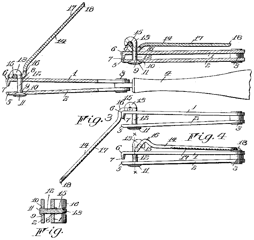
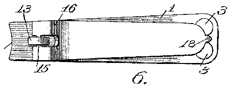
In the drawings, Figure l is a view, partly in section, showing anail-trimming device em- 3 bodying my invention, the operating-lever being in operative position. Fig. 2 is a similar view showing the operating-lever and the jaws in their relatively closed positions. Fig. 3 is a View of'the device in elevation, the operating-lever being in an intermediate position;
and Fig. 4 is a similar View showing the operating-lever in a reversed position. Figs. 5 and 6 aretop and bottom plan views, respec- O tively, of the device; and Fig. 7 is a sectional 4 view through the connecting link or pin on the line a; w of Fig. 4:.
In the several views the same numerals of reference designate similar parts.
The present embodiment of my invention comprises generally the opposing jaws 1 and 2, which are composed in the present instance of a pair of plates which are preferably made of resilient material and are united at one end 5, which conforms approximately to the curvature of the finger-tips, and the opposing jaw 1 is also provided with a similarly-formed recess 6, either or both of the jaws being provided with a cutting edge 7, which is formed to cooperate with the opposing jaw and preferably has a curvature of such a configuration as will enable the nail to be readily trimmed into the desired shape. These jaws 1 and 2 are each provided with the perforations 8 and 9, respectively, the aperture 9 of the jaw 2 being provided witha countersunk recess 10, which is preferably formed oblong, rectangular, or otherwise angularly shaped, and in this countersunk recess is adapted to fit the correspondingly-shaped head 11 of the pin or link 12, the stem of the latter extending through the apertures 8 and 9 of the jaws 1 and 2, respectively, and terminating in a curved or hooked portion 13. This curved or hooked portion of the pin or link is adapted to cooperate with an operating member 14., which in the present instance is forked at one end in such a manner as to admit the said hooked portion of the pin, a pivot 15 being provided between the forks for engaging beneath the said hooked portion of the pin, that portion of the operating member in proximity to the said pivot being disposed at an oblique angle to the body of the member in order that the extremities of the latter will constitute a relatively laterally arranged projection at one side of the said pivot 15, and the bent portion 16 will constitute a similar projection upon the opposite side of the said pivot, such an arrangement causing the projection 16 to bear against the adjacent jaw 1, and thereby move the latter toward the opposing jaw 2, when the free end of the operating member is manipulated toward the device from a position similar to that shown in Fig. 1, thus causing the sharpened cutting edge to sever that portion of the nail which it may be desirable to have removed, the jaws and the operating-lever at this time occupying a position similar to that shown in Fig. 2. When the operation of severing the nails has been completed, the operating member may be thrown over into the position shown in Fig. 3 in order that the file or roughened portion 17 and the pointed implement 18, which are preferably formed upon the operating member, may be rendered convenient and accessible for use, the jaws or body portion of the device at this time serving as a handle during this operation. By swinging the operating lever or member 14 about the pin 12 as a center until it assumes a position similar to that shown in Figs. 1 and 5 the device will occupy a comparatively small compass or space that Will enable it to be conveniently carried upon the person, and while the operating-lever occupies such a position the extremity of the said lever adjacent to the pin will be so disposed relatively to the pivot 15 of the lever that the resiliency or spring action of the jaws 1 and 2 will operate to retain the operating member closed or in immediate proximity thereto.
For the purpose of preventing the connecting-pin 12 from turning accidentally or too easily and in order to insure the proper positioning of the operating member I provide the angularlyshaped countersunk recess in which the correspondingly-shaped head upon the pin 12 rests, and as the jaws 1 and 2 are preferably so fitted together that their resilient action normally tends to separate them it will be readily understood thatfthe pressure thus produced will operate to retain the angularly-shaped head of the pin in such a position within the recess as to normally resist the turning of the pin; but when sufficient force is exerted upon the pin by manipulating the operating-lever 14 the pressure exerted between the head of the pin and the jaws will be overcome, thus permitting the pin to be rotated into its reversed position, in which positionit will be retained by the seating of the angularly-shaped head of the pin within the correspondingly-shaped portion of the recess.
A'device of the character described is particularly useful and convenient as an implement for trimming and dressing the finger and toe nails of a person, and it is so constructed as to simplify and facilitate the manipulation and operation of the device, and in practice the handle I may be employed to enable the device to be conveniently and steadily held or grasped by the hand of the operator,the handle being preferably omitted, as in Figs. 2, 3, and 4:, when it is desirable to render the device capable of being conveniently carried in the pocket or other small receptacle or space.
I claim as my invention- 1. Inadevice of the character described, the
combination with the cooperative jaws having a normal tendency to separate, and a link or connection mounted in pivotal relation with the jaws, of an operating member cooperating with the said link and having a projection thereon for'proximating the said jaws when the said member is operated in one direction, and an oppositely-arranged projection capable of being cooperatively arranged between the said jaws and link when the latter and the operating member are in a relatively reversed position to cause the separating action of the jaws to retain the said member in its closed position.
2. In adevice of the character described, the combination with the cooperatively-arranged jaws, and a link or connection mounted in revoluble relation with the said jaws, of an operating member having a pivotal connection with the said link and provided with oppositely-arranged projections one of which is capable of cooperating with the said link and jaws to proximate the latter when the operating member occupies a predetermined position, the other projection being arranged to cooperate with one of the jaws when the relative positions of the link and operating member are in a reversed position and thereby retain the said member in its closed position.
3, In a device of the character described, the combination with the cooperatively-arranged jaws having a normal tendency to separate, of a pin or link connecting said jaws having an angularly-shaped head thereon arranged to cooperate with a correspondingly-formed recess in one of the jaws to resist the rotation of the link, and an operating member cooperating with said link while the latter occupies a predetermined position to proximate the jaws, and having a projection thereon operating under the separating action of the jaws to retain the operating member in a closed position while the link and operating member o c cupy relatively reversed positions.
4. In a device of the character described, the
combination with the cooperatively-arranged jaws, and the connecting link or pin attached to one of the jaws and having a curved or hooked portion in proximity to the opposite jaw, of an operating member having a pivotal connection with the hooked portion of the pin and provided with a projection arranged to cooperate with one of the jaws to proximate the latter when the operating member is manipulated, while in one position and an oppositelyarranged projection formed to cooperate with shaped head thereon formed to fit a correspondingly-shaped recess in one of the jaws, of an operating member cooperating with the said link while the latter occupies a predetermined position to proximate the jaws, and operating under the separating action of the jaws when the link is rotated into a reversed position to remain in a closed position in proximity to the adjacent jaw.
6. In a device of the character described, the combination with the cooperatively-arranged jaws, and the connecting-link, of an operating member mounted in pivotal relation with said link and having a projection thereon arranged to cooperate with the adjacent jaw to proximate the jaws when the said member is manipulated in one direction, and an angularlydisposed portion arranged to engage the said jaw when the said member is manipulated in the opposite direction and thereby retain the said member in a predetermined position relatively to the remainder of the device.
7; In a device of the character described, the combination'with the cooperatively-arranged jaws, and the connecting-link between them, of an operating member pivotally attached to said link and provided with an angularly-disposed portion forming a projection for engaging one of the jaws for proximating the latter when the said member is manipulated in one direction, and an oppositely-arranged projection upon said angularly-disposed portion and cooperating with the said jaw when the position of the said member is reversed to retain the latter in immediate proximity to the body of the device.
FRANK B. LA MAY.
Witnesses:
F. N. HOWARD, CLARENCE A. BATEMAN.


